Flashlight Batteries and Constant-Current Driver Guide
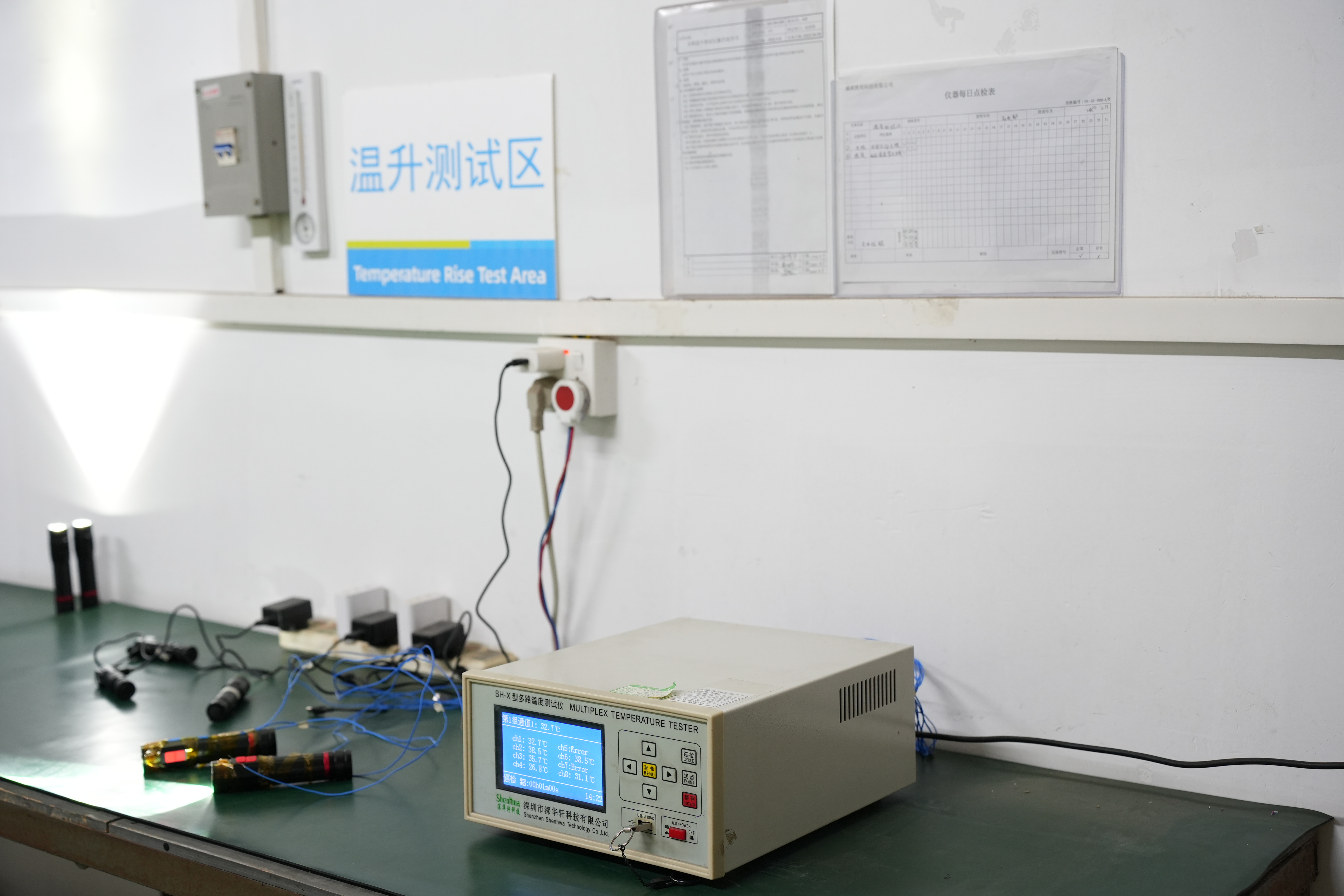
Direct answer: flashlight batteries and constant-current drivers must be designed as one electrical and thermal system. The cell supplies a changing voltage and has limits for capacity, current, temperature and protection. The driver converts that input into controlled LED current and may add modes, low-voltage behavior and thermal regulation. Output and runtime cannot be predicted reliably from battery capacity or LED rating alone; the complete flashlight must be measured with the specified cell and operating mode.
For OEM buyers, the practical task is to define the approved battery configuration, operating limits and user behavior, then verify the driver across the full input range. A high initial lumen figure is not enough. The engineering evidence should show how output changes as the battery discharges, how heat affects regulation, what protection events occur and which components or firmware revisions were used.
01.Battery Selection Starts With the Load
A battery is not just a container of milliamp-hours. It has a voltage range, internal resistance, current capability, temperature behavior, cycle-life profile and protection requirements. When the LED driver draws current, the cell voltage drops according to state of charge, load and internal resistance. A cell that performs adequately at low output may sag or heat at a higher mode, causing early step-down or protection cutoff.
Rechargeable lithium-ion formats are common in higher-output portable lights because they offer useful energy density and current capability. Primary alkaline or lithium cells can suit long storage, field replacement or lower-power designs. Nickel-metal hydride cells remain relevant in some replaceable-battery products. The correct chemistry and format depend on output target, storage period, charging approach, operating temperature, logistics and user expectations.
Cell dimensions such as 18650 or 21700 identify approximate physical format, not guaranteed quality or performance. Cells with the same size and printed capacity can differ substantially in current capability, protection, authenticity and consistency. The approved cell list should name the manufacturer and part number or define controlled, validated alternatives.
Mechanical compatibility is part of electrical performance
A cell can be electrically suitable yet mechanically incompatible. Protected cells may be longer than unprotected versions; button-top and flat-top terminals change contact geometry; wrapping damage can create insulation risk; and a loose cell can interrupt power under impact. Springs, contact plates and battery tubes must accommodate the approved tolerance range without crushing the cell or allowing excessive movement.
Contact resistance also converts electrical energy into local heat and voltage loss. Surface finish, spring force, contamination and repeated battery replacement can change that resistance. Validation should include the complete current path—from cell terminals through contacts, wiring and driver input—not only the cell and PCB on a bench supply.
02.What a Constant-Current LED Driver Does
An LED responds strongly to current and temperature. Connecting a high-power LED directly to a battery does not provide stable or safe control. A constant-current driver regulates current through the LED so the intended operating point can be maintained within the available input voltage, component limits and thermal conditions.
The driver topology depends on the relationship between battery voltage and LED forward voltage. A buck stage reduces a higher input voltage; a boost stage raises a lower input; and a buck-boost architecture can regulate when the input crosses above and below the required output level. Linear regulation can be simpler in suitable voltage ranges but dissipates the unused voltage as heat. No topology is automatically best—the decision involves efficiency, size, cost, electromagnetic behavior, control range and component stress.
Modes may be created by changing regulated current, using pulse-width control or combining methods. Firmware can manage mode order, memory, lockout, low-voltage warning and thermal response. These features must be verified as part of the driver, not treated as independent labels. A firmware change can affect current, runtime, step-down timing and user interface even when the housing and LED remain unchanged.
03.How the Battery and Driver Interact
| System variable | What changes | Possible flashlight response | Evidence to review |
|---|---|---|---|
| Battery state of charge | Available voltage and energy decrease | Regulation changes, warning or cutoff | Output and input-current curves over discharge |
| Higher LED mode | Input current and heat rise | Shorter runtime, voltage sag or thermal step-down | Current, temperature and output versus time |
| Cold battery | Internal resistance can increase | Reduced peak capability or earlier cutoff | Environmental performance with approved cell |
| Cell substitution | Capacity, protection and current limit may differ | Changed output, runtime or safety margin | Approved-cell matrix and change assessment |
| Thermal limit | Sensor or firmware threshold is reached | Current reduces until temperature recovers | Thermal-control logic and stabilized output |
This interaction explains why one product may be compatible with several cells but deliver its rated performance only with an approved configuration. Product categories such as the flashlight range and tactical flashlights should lead buyers to model-specific battery and driver data, not a category-wide electrical assumption.
04.Runtime, Efficiency and Thermal Regulation
A simple watt-hour calculation can estimate available energy, but it cannot predict finished runtime by itself. Driver efficiency changes with input voltage and load; the LED’s electrical and optical efficiency changes with current and temperature; auxiliary electronics consume power; and low-voltage protection leaves some energy unused. Battery capacity is also measured under specified conditions that may differ from the flashlight load.
Runtime should therefore be evaluated with the complete product, approved battery, defined mode and controlled ambient conditions. The full output-versus-time curve is more informative than one endpoint because it shows initial behavior, regulation, thermal step-down and end-of-discharge response. For a task light or emergency product, the minimum useful output at a particular time may matter more than the first minute’s peak.
Thermal regulation is not automatically a defect. Reducing current can protect the LED, driver, battery and surfaces when heat cannot be removed quickly enough. The engineering question is whether the control is predictable and appropriate for the intended use. Request temperature locations, ambient condition, sample orientation, airflow assumptions and stabilized output. SHENGQI LIGHTING’s testing context can support a project discussion, while the exact method and result still need model-level confirmation.
05.Protection and Charging Questions for OEM Buyers
Protection can exist in the cell, battery pack, driver, charging circuit or a combination. Relevant functions may include overcharge, over-discharge, overcurrent, short-circuit and temperature control. The correct architecture depends on whether the battery is fixed, removable, user-supplied or sold as a matched pack. Protection thresholds and recovery behavior should be coordinated so one subsystem does not create an unexpected failure mode in another.
A USB connector does not, by itself, define the charging protocol, input power or charge algorithm. Confirm connector type, supported inputs, charge current, termination behavior, temperature monitoring, indicator logic and operation while charging. If the product can run during charging, test the additional heat and power-path behavior. The approved cable and adapter conditions should be stated without implying compatibility that has not been verified.
- Approved battery manufacturer, part number, chemistry, configuration and protection status.
- Driver schematic or controlled functional specification, PCB revision and firmware version.
- LED current, input current, efficiency and output across the specified battery-voltage range.
- Runtime curves, thermal behavior, low-voltage warning and cutoff verification.
- Charging profile, protection tests, component change control and applicable market requirements.
These items belong in the technical agreement for a custom program. The OEM and ODM service process is the correct next step for project-specific configuration and evidence.
06.Frequently Asked Questions
Review Battery, Driver and Runtime Evidence Together
Share the target output, runtime, battery, charging and environmental requirements so the electrical architecture can be evaluated as one product.
Contact the Engineering Team