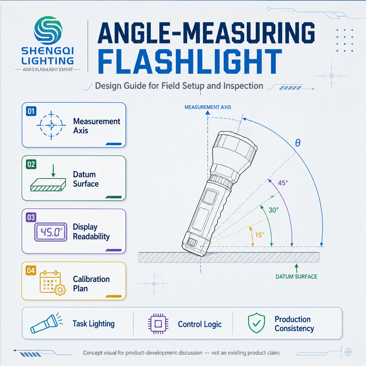

What Is an Angle-Measuring Flashlight?
An Angle-Measuring Flashlight is a portable tool concept that combines task illumination with a system for measuring or displaying the orientation, tilt or angle of the tool or a referenced surface. Unlike a simple level reference, the goal is to give the user a measurable angle reading that can support setup, adjustment or inspection.
One possible architecture uses an electronic orientation sensor with processing electronics and a display, but the sensing method is project-specific. The product could support equipment setup, HVAC installation, conduit or pipe positioning, equipment-frame adjustment, solar-panel positioning support, sign installation or other field tasks where lighting and angle information are needed at the same point.
Existing portable tooling light platforms can provide references for task-lighting architecture, but they should not be described as existing angle-measuring products.
Start With the Angle the User Actually Needs to Measure
Do not begin with “add a digital sensor.” Begin with the physical job.
What is being adjusted? What angle range is relevant? Does the user need absolute orientation or a relative comparison between two surfaces? Is the tool placed directly against the workpiece, held in the hand or mounted magnetically? How often is the measurement taken? Does the reading only need to be viewed, or must the workflow preserve a value after the tool is moved?
Required accuracy, resolution, operating environment and measurement frequency should all come from that use case. Measurement architecture follows the task.
Angle Measurement Is Not the Same as a Simple Level Reference
A leveling function primarily answers a basic alignment question: is the referenced surface level or vertical? An angle-measuring function answers a different question: what is the measured orientation or inclination?
That distinction matters for product planning and SEO. A product intended only for quick horizontal or vertical alignment does not need to become a numerical angle instrument. Conversely, a digital angle tool needs a defined measurement axis, calibration plan and evidence that supports the reading shown to the user.
The Measurement Axis Must Be Defined Before the Housing Is Designed
What does the displayed angle actually represent? It could be tied to the bottom surface, side surface, flashlight centerline, magnetic base, mounting face or another engineered datum.
If that relationship is unclear, even a stable electronic reading can become confusing. A user may place the product against one surface while the internal measurement axis represents something else.
The numerical angle only has meaning when it is tied to a defined physical reference on the product.
A Digital Sensor Still Depends on Mechanical Geometry
An electronic sensor can produce a repeatable signal while the physical measurement remains inconsistent. A warped housing face, protruding clip, uneven magnetic base, loose bracket or assembly variation can change how the product contacts the workpiece.
Sensor performance, mechanical datum and assembly consistency therefore have to be reviewed as one measurement system. Digital does not automatically mean more accurate.
Brands exploring enclosure directions can review portable lighting product platforms for general body and control architectures without treating existing products as angle-measuring tools.
The Angle Reading Must Be Easy to Read Without Moving the Tool
Display position is part of the measurement workflow. Digit size, contrast, backlight, viewing angle, daylight readability and nighttime brightness all affect whether the user can read the result while the datum remains in contact with the workpiece.
Automatic screen rotation could be useful for some orientations, but it is a design option rather than a default requirement.
If the user has to move the tool away from the reference surface to read the angle, the interface is working against the measurement task.
The Beam Should Illuminate the Adjustment Area Without Hiding the Measurement
During installation, the light may need to reveal fasteners, mounting points, contact surfaces, reference edges or the area being adjusted. Peak output is less useful than a beam that supports the actual working distance.
Buyers should evaluate low and medium modes, beam spread, hotspot behavior, spill, display reflection and shadows created by the user's hand or the tool itself.
The lighting subsystem and measurement interface should be tested together. A bright beam that creates glare on the screen or reflective workpiece can make an otherwise useful angle tool harder to operate.
Sensor Choice Should Follow the Required Measurement, Not Marketing Language
An electronic angle function may involve orientation sensing, signal processing, a zero reference and a display output. The actual sensing architecture should be selected according to the required measurement range, resolution target, accuracy target, response behavior, temperature environment, shock exposure and power budget.
No single sensor type should be treated as automatically superior without the product requirement.
Absolute and Relative Angle Are Different Workflows
An absolute-orientation workflow references gravity or another defined system reference. A relative-angle workflow may allow the user to establish one surface as zero and then compare another surface against it.
If the product brief requires relative measurement, a zero or reference workflow may be necessary. That function should be defined from the physical task rather than added simply because other digital measuring tools include it.
An Angle-Measuring Function Needs a Calibration and Verification Plan
Before a buyer approves a digital angle claim, the project needs answers to basic engineering questions: What accuracy and resolution are required? How is zero established? Which physical surface is the datum? Does the product need factory calibration, user zeroing or both? How will drift, temperature and post-impact behavior be checked?
A digital display is not evidence of measurement accuracy.
Calibration and product verification should be linked to the final housing, datum, electronics and assembly. General product verification capabilities can support a development process, but this article does not claim that an existing SHENGQI system already performs angle calibration.
Lighting Controls and Measurement Controls Should Not Compete
A multifunction product may need actions for flashlight power, brightness, measurement electronics, zero or reference functions, hold, unit selection or display behavior. Those are potential UI functions, not requirements that every product should include.
Buyers should define which actions deserve dedicated buttons, whether lighting and measurement share controls, how accidental zeroing is prevented and whether the tool can be operated one-handed in darkness.
A Hold or Freeze Function Should Follow the Physical Workflow
If the user must remove the tool from a narrow or difficult position before reading the result, a hold or freeze function may be useful. If the display remains visible during measurement, that feature may add unnecessary complexity. UI should follow the physical workflow.
Magnetic Positioning Can Stabilize the Tool, but the Magnet Is Not the Measuring Reference
A magnetic structure may support temporary attachment, hands-free reading and stable positioning on a suitable ferromagnetic surface. It does not determine the angle reading.
The measurement still depends on the sensor, datum surface, measurement axis and contact geometry. Buyers should test holding force, sliding, surface material, orientation, vibration and whether the magnetic structure changes the contact angle.
Clips, lanyards, brackets and other accessories also need to be reviewed early if they can obstruct a reference face or alter how the tool contacts the workpiece.
Battery and Thermal Design Matter to Both Lighting and Measurement Electronics
An Angle-Measuring Flashlight may need to power the LED, driver, sensor, processor, display and backlight. Battery capacity alone therefore does not establish usable runtime.
Product teams should define representative light modes, measurement frequency, display behavior, standby time, session duration and charging workflow before selecting the battery architecture.
Higher light output can also change the internal thermal environment. Whether that affects measurement stability depends on the final electronics and mechanical design and should be evaluated on the prototype rather than assumed.
Environmental and Post-Impact Verification
Construction, workshop and outdoor-maintenance products may need project-specific targets for dust, rain, temperature and impact. Final ingress-protection, impact and operating-temperature targets should be defined for the finished product.
A flashlight can survive a drop and still turn on while its measurement reference has changed. If impact testing is part of the project, zero, datum relationship and angle repeatability should be rechecked afterward.
Angle-Measuring Flashlight Product Specification Matrix
| Design Area | Buyer Question | Engineering Decision | Prototype Verification | Main Risk |
|---|---|---|---|---|
| Measurement Type | Absolute, relative or both? | Measurement workflow | Task-based comparison | Wrong measurement concept |
| Angle Range | What range does the task need? | Project-defined sensor requirement | Representative-angle checks | Overspecified or unusable range |
| Measurement Axis | What does the reading represent? | Axis-to-housing definition | Axis verification | Ambiguous reading |
| Datum Surface | What contacts the workpiece? | Mechanical reference geometry | Contact-surface check | Mechanical error dominates sensor |
| Accuracy / Resolution Target | What does the application require? | Project-specific target | Defined comparison method | Display implies unsupported precision |
| Display | Can the reading be seen in position? | Location, contrast and brightness | Day / dark readability | User moves tool to read |
| Task Lighting | Does the beam support adjustment? | Mode and beam strategy | Beam / glare review | Display or workpiece glare |
| Controls | Can functions be used without errors? | Button and UI architecture | One-hand / accidental-zero test | Measurement reset unintentionally |
| Magnetic / Mounting Structure | How is the tool positioned? | Mount and datum integration | Holding / geometry check | Mount changes reference angle |
| Battery | How long is the combined workflow? | System power architecture | Representative-use test | Capacity mistaken for runtime |
| Thermal / Environmental Requirement | What field conditions apply? | Project-specific limits | Thermal / environmental evaluation | Measurement behavior not verified |
| Calibration / Production Verification | How will readings remain consistent? | Calibration and QA plan | Production-representative comparison | Prototype result not reproduced |
Twelve Tests Buyers Should Run on an Angle-Measuring Flashlight Prototype
Confirm repeatable contact between the defined datum and representative workpieces.
Verify the project's defined zero or reference condition.
Repeat placement and measurement using the same reference condition.
Compare readings across representative positions defined by the project.
Evaluate the zero-and-compare workflow on representative surfaces.
Check viewing angle, contrast and hand position outdoors.
Evaluate backlight and glare without moving the product.
Review interaction between the light beam, display and reflective work surfaces.
Operate the tool repeatedly and check for unintended resets.
Evaluate holding, sliding and datum contact on representative surfaces.
Recheck zero, datum relationship and repeatability after applicable durability testing.
Compare complete measurement behavior across representative builds.
Acceptance criteria are project-specific.
Ten Questions Before Developing an Angle-Measuring Flashlight
- What exact installation or inspection task requires angle measurement?
- Does the user need absolute angle, relative angle or both?
- Which physical surface defines the measurement axis?
- What angle range, accuracy and resolution are actually required?
- How should the display remain readable without moving the tool?
- How will illumination avoid creating glare on the display or workpiece?
- Does the product need magnetic mounting, hold, zero or other workflow functions?
- What battery architecture supports lighting and measurement together?
- How will calibration and post-impact accuracy be verified?
- How will the approved prototype be matched to mass production?
Manufacturing Consistency Is Part of Measurement Accuracy
Angle performance can be affected by sensor placement, PCB mounting, housing geometry, magnetic structures, brackets, adhesives, screws, datum machining and tolerance stack. Reviewing only the sensor specification is not enough.
A project should connect Sensor + Mechanical Datum + Assembly + Calibration + Final Verification as one controlled system.
That relationship should continue through sample-to-production manufacturing, with the approved geometry and electronics revision carried into representative production verification.
How an OEM/ODM Project Should Approach an Angle-Measuring Flashlight
Measurement requirements must be defined before industrial design is frozen. The project may involve Industrial Design, Optical Engineering, Electronic Design, PCB Layout, sensor integration, display and UI development, Mechanical Datum Design, battery architecture, thermal design, prototype verification, manufacturing, Quality Control and Packaging Design.
For a custom Angle-Measuring Flashlight project, the measurement subsystem would need to be integrated and validated together with the portable-lighting architecture. Starting with an attractive housing and trying to insert the sensor afterward can create problems with datum definition, display visibility, controls and calibration.
SHENGQI LIGHTING can support the portable-lighting and broader product-development side through its custom flashlight development capabilities. No existing SHENGQI angle-measuring model, sensor platform, measurement range, accuracy or calibration result is claimed here.
Frequently Asked Questions About Angle-Measuring Flashlights
1. What is an angle-measuring flashlight?
An angle-measuring flashlight is a portable tool concept that combines task illumination with a system for displaying or measuring the orientation, tilt or angle of the tool or a referenced surface. Its useful performance depends on more than adding a sensor. The measurement axis, datum surface, display, lighting, controls, calibration and mechanical assembly all need to support the same field workflow.
2. How is an angle-measuring flashlight different from a leveling flashlight?
A leveling flashlight primarily supports basic alignment questions such as whether a surface is level or vertical. An angle-measuring flashlight is intended to provide a measurable or numerical orientation or inclination value. That creates additional requirements for the measurement axis, sensor performance, display, calibration and production verification. The two concepts may overlap in installation work, but they should not own the same search intent.
3. What types of angles can an integrated measuring tool be designed to check?
The project may be designed around absolute orientation, relative angle between two surfaces or both, depending on the task. Equipment setup, HVAC installation, conduit positioning, pipe setup, brackets and field equipment adjustment can require different workflows. The required measurement range and reference should be defined from the actual application rather than assumed from a generic digital-angle-tool specification.
4. Does a digital angle display guarantee measurement accuracy?
No. A digital display only presents the processed measurement result. Accuracy depends on the defined datum, sensor performance, calibration, mechanical geometry, assembly consistency, environmental behavior and supporting test evidence. A high-resolution display can show more digits without proving that the underlying measurement is equally accurate. Buyers should define the required accuracy separately and verify it on the final product configuration.
5. Can magnetic mounting improve angle-measurement accuracy?
A magnet can stabilize the tool on a suitable ferromagnetic surface and make hands-free reading easier, but it does not determine measurement accuracy. The reading still depends on the sensor, datum surface, measurement axis and contact geometry. Buyers should verify holding force, sliding, surface material and whether the magnet or mounting structure changes how the product contacts the measured surface.
6. What should B2B buyers test on an angle-measuring flashlight prototype?
Buyers should test the datum surface, zero reference, repeatability, representative angles, display readability, beam glare, controls, relative-angle workflow where required and magnetic positioning where applicable. Post-impact verification is also important when durability testing is part of the project. Production-representative samples should then be compared with the approved prototype using project-specific acceptance criteria.
7. Can an angle-measuring flashlight be customized for OEM/ODM projects?
Yes. A custom project can define the angle-measurement workflow, datum, sensing architecture, display, lighting, controls, battery, magnetic or mounting features and environmental requirements as one system. The measurement requirements should be established before the housing is frozen. Prototype verification, calibration planning and production control then need to connect the electronics and mechanical reference throughout development.
Build the Measurement System Around the Field Workflow
A useful Angle-Measuring Flashlight should connect the measurement task, physical datum, sensing system, display, task beam, controls and calibration plan before production decisions are frozen. Numerical output adds value only when the user understands what the reading represents and the approved geometry can be reproduced consistently in production.
Define the Measurement Requirement Before Freezing the Product Architecture
Tool brands, hardware companies, installation-equipment businesses and private-label buyers can discuss task lighting, mechanical datum design, display and UI requirements, sensor integration, battery architecture, prototype verification and manufacturing consistency.
Contact SHENGQI LIGHTING for an OEM/ODM technical evaluation at sales@shengqilight.com.
Contact SHENGQI LIGHTING