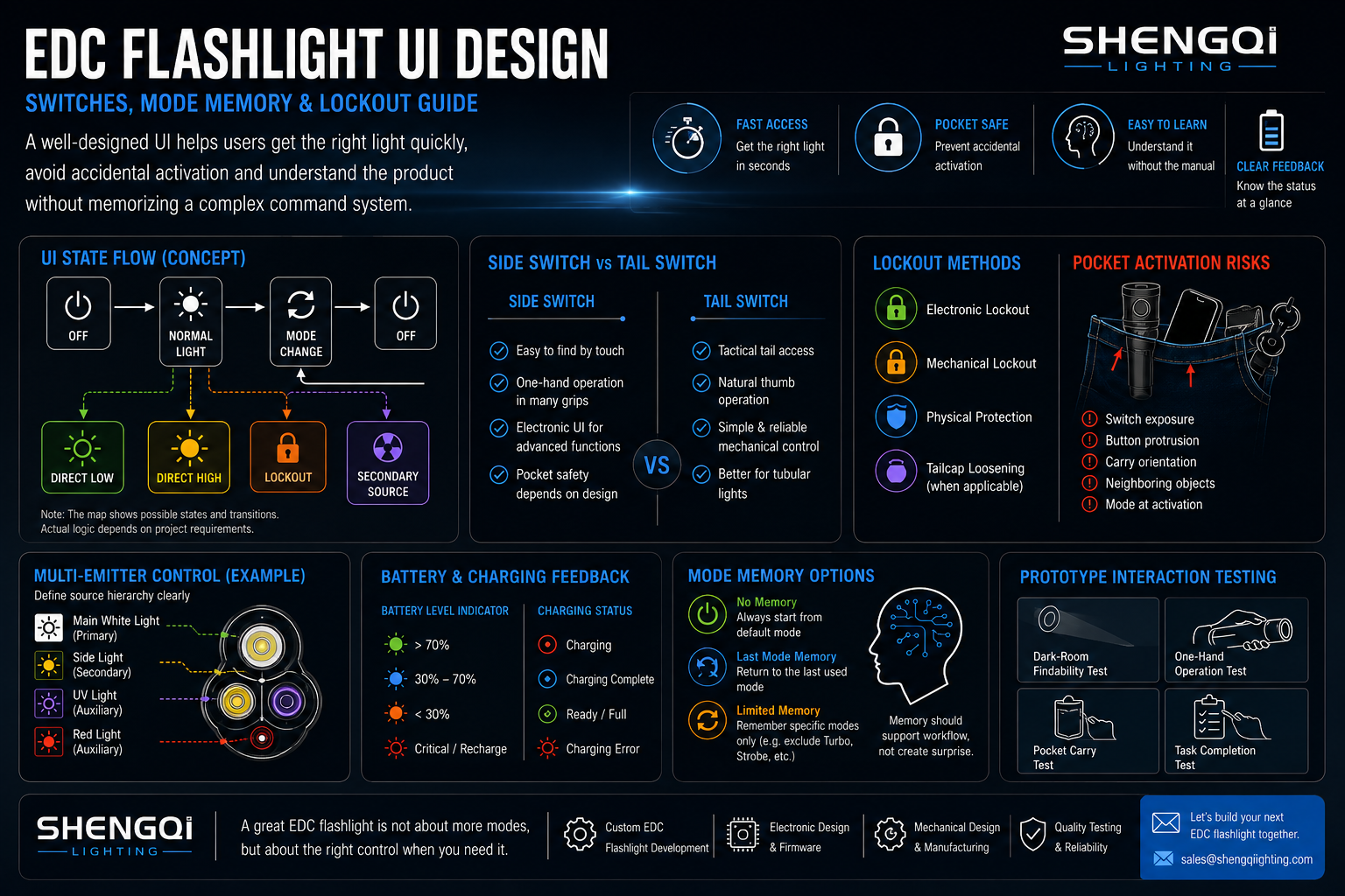

What Is EDC Flashlight UI Design?
An EDC flashlight UI includes the physical switch, its position, tactile feedback, click and hold behavior, mode order, memory, lockout, source selection, status indication and charging feedback. Buyers comparing EDC flashlight product platforms should therefore evaluate interaction architecture as carefully as output or battery capacity.
The switch is hardware; the user interface is the complete relationship between the user's action and the flashlight's response.
An RFQ that says only “5 Modes” leaves major behavior undefined. Which mode starts first? Does the light remember the previous state? What does double click do? How is lockout entered and exited? How are UV, red or side lights selected? What happens after battery removal? What does the indicator mean? Mode count does not describe control logic.
Start UI Design With the First Action
Ask what the user should receive immediately after taking the light from a pocket. A general EDC product may need a normal working level. An inspection-oriented light may favor low or medium output. A high-output product may define another main state. A low-light application may prioritize a low-output source. First-click behavior should follow the primary task.
OFF-state actions and already-ON actions should be specified separately. A short click from OFF may start the product, while a short click during operation may change modes or turn it off. Do not reduce the UI brief to Mode 1 → Mode 2 → Mode 3.
OFF → NORMAL LIGHT → MODE CHANGE → OFF
Possible side paths: Direct Low · Direct High · Lockout · Secondary Light. The point is to document states and transitions before sampling, not to prescribe these exact commands.
Switch Architecture Shapes How the Flashlight Is Used
Mechanical tail switches, electronic side switches, dual-switch systems, rotary controls, twist controls and project-specific combinations can all be valid. The correct architecture depends on carry, grip, direct-access needs, glove use, lockout requirements and control complexity.
Mechanical vs Electronic Switch
A mechanical switch can provide a clear physical action and, in some architectures, direct circuit interruption. Its available UI behaviors may be more constrained. An electronic switch can support richer shortcuts, lockout, indicators and firmware-defined logic, but it introduces standby electronics and more state behavior to specify. Simple mechanical architecture can be the correct UI when the task values predictability over feature density.
Side Switch vs Tail Switch Is a Carry-and-Grip Decision
| Design Area | Side Switch | Tail Switch | Buyer Question |
|---|---|---|---|
| 1. Grip Orientation | Body-side access | End-of-body access | How is the light normally held? |
| 2. Pocket Carry | Side exposure depends on geometry | Tail exposure depends on clip orientation | What presses against the switch? |
| 3. Find by Touch | Texture and recess matter | End position can aid orientation | Can users locate it in darkness? |
| 4. One-Hand Use | Depends on grip position | Depends on thumb/finger access | Can primary tasks be completed one-handed? |
| 5. Accidental Activation | Affected by protrusion and recess | Affected by tail geometry | What is the carry risk? |
| 6. Glove Access | Button size and feedback matter | Actuator shape matters | Is glove operation required? |
| 7. Direct Access | Can support electronic shortcuts | Depends on switch architecture | Which shortcuts are truly needed? |
| 8. Body Length | Side packaging affects internal layout | Tail mechanism occupies end space | What packaging trade-off exists? |
| 9. UI Complexity | Potentially richer firmware states | Can remain simpler or use dual controls | How many states must users learn? |
| 10. Product Role | Good fit for many compact electronic designs | Good fit for many tubular designs | Which role should control architecture serve? |
No universal winner exists. In darkness, switch findability also matters. Position, texture, shape, recess, surrounding geometry and clip orientation can help the user identify a control by touch. A button that looks clean in a rendering may be difficult to find by touch.
Modes Need a Hierarchy, Not Just a List
PRIMARY MODES are used frequently. SECONDARY MODES support less frequent tasks. SPECIAL MODES may be rare. Low, Medium, High, Turbo, Strobe, UV, Red and Side Light should not automatically share equal status in one linear cycle. Frequently used modes should be easier to reach than rarely used modes.
How many modes are too many? Too many modes exist when users must repeatedly cycle through irrelevant outputs to reach the light they actually need.
Direct Access Is More Valuable Than More Modes
Direct access means reaching a defined priority state from OFF without cycling through unrelated modes. Depending on the project, that may be low, high, Turbo or a secondary emitter. The trade-off is fast access vs command complexity.
Double click, long press and triple click are UI tools, not premium features. If users must memorize several unrelated combinations, the shortcut system becomes another burden. Shortcut logic should be internally consistent.
Mode Memory Can Be Helpful—or Annoying
No Memory creates predictable startup. Last-Mode Memory can support repetitive workflows. Limited Memory can remember selected normal modes while excluding special states. None is universally superior.
Memory scope must also be specified. Does the product remember brightness only, the emitter source, red/white selection, an auxiliary mode or nothing? “Has memory” is not enough. Reset conditions should also be documented: battery removal, long power-off, lockout, charging or another project-defined event may change memory behavior.
Lockout Should Solve a Carry Problem
Electronic lockout, mechanical lockout, slight tailcap loosening where electrically appropriate, recessed switches and protected button geometry are all possible approaches. Lockout is one solution to accidental activation, not the definition of a safe carry design.
Electronic lockout can create another problem if users forget how to exit it. The unlock action should be simple enough for the intended user to rediscover or follow from instructions. A four-click sequence is not automatically good or bad; it must be judged within the whole UI.
EDC Flashlights Have to Survive the Pocket
Fabric pressure, keys, tools, phones, body movement, sitting and bag compression can all interact with a switch. Representative carry evaluation should consider switch protrusion, recess, stiffness, clip orientation, body geometry and lockout behavior.
Accidental Activation Risk Map: accidental entry into the highest-output state can create a different risk profile from accidental low-mode activation. Startup behavior and pocket protection therefore should not be designed separately.
Multi-Emitter EDC Lights Need Source Hierarchy
Main white, side light, red, UV or another auxiliary emitter should not automatically be treated as equal states. Buyers should define which source is primary, which is secondary, how source switching works, whether memory includes source selection and whether an auxiliary source can be entered from OFF.
Source selection and brightness selection should be treated as separate UI decisions.
| Architecture | How It Works | Main Trade-Off |
|---|---|---|
| Source-First UI | Select Main / Side / Red / UV, then choose brightness where applicable | Clear hierarchy but adds source-selection step |
| Mode-First / Unified UI | Functions share one sequence | Fewer controls but can increase cycling cost |
| Dedicated Control | Different sources use separate controls | Lower state ambiguity but more hardware and button area |
Y1 illustrates why this matters: it combines a main white light, UV and side light with a built-in 1000mAh battery and a flat rectangular body. Y4 combines spot, flood and UV in a compact 58 × 28 × 28.29mm body weighing 52.4g including battery. Their confirmed architecture shows the control problem; it does not establish any specific button sequence.
The Flashlight Should Tell the User What State It Is In
Indicator LEDs, color indicators, displays, blink patterns or illuminated switches can communicate battery status, charging, lockout, source selection or low-voltage state. More feedback is not automatically better.
Status feedback should reduce uncertainty, not create a second code system the user must memorize. If red, blue and green flashes represent ten different states, the feedback system may require its own manual.
Build a UI Language Across the EDC Product Line
Brands with multiple SKUs should consider whether common actions share a recognizable control language. Click = On/Off, Hold = Secondary Function, Double Click = High-Priority Shortcut and a consistent lockout pattern are examples of a conceptual family framework, not mandatory commands. Consistency reduces re-learning across SKUs.
Battery and Charging Feedback Are Part of the Interface
The user may need to know: Is it charging? Is charging complete? Is the battery low? Is the product locked? Can it operate while charging if the architecture permits? Exact indicator behavior remains project-specific.
A numerical battery display is not automatically superior. Battery estimates depend on voltage, load, algorithm and cell behavior, so displayed information should be validated against the actual battery system. Feedback should match the information the user genuinely needs.
Simple UI vs Feature-Dense UI
| Area | Simple UI | Feature-Dense UI |
|---|---|---|
| Learning | Lower command burden | More states to remember |
| Direct Access | Fewer shortcuts may be needed | Shortcuts may protect frequent tasks |
| Emitters / Modes | Narrower role | More source and mode decisions |
| Firmware | May be minimal | Usually more state logic |
| Target User | Predictability-focused workflow | Users who need added behaviors |
Complexity is justified only when the product needs the additional behavior.
Control Budget
Compact EDC products have limited button area, hand positions and memory burden. Every new emitter, shortcut, mode, indicator, display or gesture consumes part of that limited interaction capacity. Every function consumes part of the control budget.
| Feature | Hardware Cost | UI Cost | Learning Cost | Validation Cost |
|---|---|---|---|---|
| Turbo | Power / thermal capability | Shortcut or hierarchy decision | Remember access path | Verify activation behavior |
| Moonlight | Low-current control | Direct-low decision | Learn low shortcut | Confirm startup and stability |
| Red Light | Additional emitter | Source-selection logic | Remember source path | Verify source states |
| UV | Additional emitter / optics | Separate source logic | Remember access | Verify state isolation |
| Side Light | Emitter / window / PCB | Source hierarchy | Learn source access | Verify source selection |
| Mode Memory | Firmware state storage | Startup logic | Predict remembered state | Test reset conditions |
| Lockout | Mechanical or electronic provision | Entry / exit logic | Remember unlock method | Pocket and recovery test |
| Battery Display | Display / sensing hardware | Information hierarchy | Interpret state | Validate battery estimate |
Existing Architectures Show Why UI Requirements Differ
G8 offers 400 / 180 / 50 / 20 / 2LM brightness levels in a compact φ30 × 64mm, 32g platform with a 290mAh lithium battery. That range demonstrates why brightness levels need hierarchy, without establishing how its actual UI is implemented.
L2 MAX provides a useful contrast through its compact tubular architecture, mechanical tail switch, 570 / 110 / 3LM steady levels plus strobe and a 14500 battery platform. Mechanical control should not be treated as a lesser architecture when predictability is more important than feature density.
Across Y1, Y4, G8 and L2 MAX, body geometry, emitter count and switch architecture all change the available control budget. Buyers can compare the wider portable lighting product range before defining a new interaction brief.
EDC Flashlight UI Decision Matrix
| UI Area | Buyer Question | Design Option | Main Trade-Off | Prototype Evidence |
|---|---|---|---|---|
| 1. Primary Switch | What action dominates? | Mechanical / electronic / other | Predictability vs feature range | Task test |
| 2. Switch Position | Where does the hand find it? | Side / tail / other | Carry vs grip | Dark-room findability |
| 3. First Click | What should happen from OFF? | Project-defined startup | Speed vs predictability | First-action test |
| 4. Mode Order | Which states are frequent? | Primary / secondary / special | Access vs cycling cost | Mode-cycling test |
| 5. Direct Low | Is low a priority? | Shortcut / no shortcut | Speed vs command count | Direct-low test |
| 6. Direct High / Turbo | Is maximum output urgent? | Shortcut / normal hierarchy | Access vs accidental activation | Shortcut test |
| 7. Mode Memory | Should startup repeat? | None / last / limited | Workflow vs surprise | Memory test |
| 8. Memory Scope | What exactly is remembered? | Brightness / source / none | Convenience vs state ambiguity | Reset-condition test |
| 9. Lockout | How is carry protected? | Electronic / mechanical / geometry | Protection vs access | Pocket test |
| 10. Accidental Activation | What can press the control? | Recess / stiffness / lockout | Findability vs protection | Representative carry review |
| 11. Secondary Emitter Access | How is source changed? | Source-first / unified / dedicated | Button count vs command burden | Source test |
| 12. Status Indicator | What state must be known? | LED / display / pattern | Information vs overload | Interpretation test |
| 13. Battery Feedback | What level must users know? | Simple indicator / display | Accuracy vs complexity | Battery-state validation |
| 14. Charging Feedback | What must be communicated? | Charging / complete / fault states | Clarity vs indicator complexity | Charging test |
| 15. Product-Line Consistency | Should actions match other SKUs? | Shared UI language / product-specific | Consistency vs specialization | Cross-SKU task test |
Five Ways an EDC Flashlight UI Can Fail Even When the Hardware Is Good
01. The First Click Starts in the Wrong Mode for the Main Task
A technically valid startup can still be poorly matched to use. A close-range product that regularly starts in an unexpectedly bright state may force an immediate correction. The hardware works, but the first interaction creates friction. Define startup around the primary workflow.
02. Too Many Modes Share One Linear Cycle
Every added state pushes frequently used modes farther apart. Users may cycle through special functions simply to reach the next normal brightness. The problem is not the existence of features; it is their equal placement in the hierarchy. Separate frequent and rare functions where the architecture supports it.
03. Mode Memory Creates an Unexpected Startup
Memory can save steps until the user forgets the last state. A remembered high-output or auxiliary mode may not match the next task. This is why memory scope and reset behavior belong in the specification. “Memory on” is incomplete.
04. Lockout Exists, but Users Cannot Remember How to Exit It
A lockout that prevents accidental activation but also prevents the owner from quickly using the product creates another failure mode. The command may be valid yet difficult to rediscover after weeks of non-use. Unlock logic should be evaluated through repeated-use testing, not only engineering familiarity.
05. Multiple Emitters Have No Clear Source Hierarchy
When main white, side, UV, red or other emitters share one undifferentiated cycle, the user may not understand whether a click changes brightness or changes source. The interface becomes harder to predict. Source hierarchy and mode hierarchy should be specified separately.
Twelve Questions Before Developing an EDC Flashlight User Interface
1. What is the user's most common lighting task? Define the task before the control scheme. Frequent actions deserve the shortest path.
2. What should happen on the first activation from OFF? Specify the starting source and brightness behavior instead of letting the prototype decide by accident.
3. Which modes are primary and which are secondary? Separate daily working modes from special functions so they do not compete equally for access.
4. Does the product need direct access to low or high output? Add a shortcut only when the task justifies the additional command.
5. Should the light remember the previous mode? Compare repeated-work convenience with predictable startup.
6. If memory is used, exactly what state should be remembered? Brightness, source and auxiliary modes are different memory scopes.
7. How will accidental pocket activation be controlled? Review switch exposure, clip orientation, recess and startup state together.
8. Does the product need an electronic or mechanical lockout? Choose the solution around carry architecture rather than a feature checklist.
9. How should multiple light sources be selected? Define source selection separately from brightness selection.
10. What battery, charging and lockout information must be communicated to the user? Feedback should answer real decisions rather than display every internal state.
11. Should the UI follow an existing control language across the brand's other products? Shared patterns can reduce learning while individual products may still need exceptions.
12. How will the approved UI and firmware revision be controlled through mass production? Freeze behavior with the approved engineering sample and revision documentation.
Do Not Send This to the OEM:
Fifteen Tests Buyers Should Run on an EDC Flashlight UI Prototype
01. Dark-Room Switch-Findability Test — Can users locate and identify the control by touch?
02. First-Click Behavior Test — Does activation deliver the intended primary state?
03. One-Hand Operation Test — Can frequent tasks be completed with the normal grip?
04. Mode-Cycling Test — How many irrelevant states separate frequent modes?
05. Direct-Low Access Test — if applicable — Can low output be reached predictably from OFF?
06. Direct-High / Turbo Access Test — if applicable — Is high-priority access fast without creating accidental activation problems?
07. Mode-Memory Test — Does remembered startup match the specification?
08. Memory-Reset Condition Test — Verify behavior after applicable power, charging or lockout states.
09. Lockout Entry Test — Can the user intentionally protect the light for carry?
10. Lockout Exit Test — Can the user regain access without excessive recall burden?
11. Pocket Accidental-Activation Evaluation — Evaluate representative carry orientation and surrounding objects.
12. Multi-Emitter Source-Selection Test — if applicable — Confirm that source and brightness changes are understandable.
13. Battery / Charging Indicator Test — Verify that feedback matches actual states.
14. Repeated-Use Learning Test — Have representative users complete core tasks, then repeat them after a period without instructions. This is a practical product evaluation, not a formal ergonomics standard.
15. Production-Representative UI Comparison — Compare switch feel, logic, indicators and firmware behavior with the approved sample.
Do not ask only, “Do you like the interface?” Ask the participant to turn on a normal working level, reach the lowest useful light, lock the product for pocket carry, unlock it, access the secondary source and check battery status. Observe whether the task is completed and where hesitation occurs. Task success is more useful than asking whether the UI “feels intuitive.”
Relevant portable-light testing capabilities can support project verification, but the UI acceptance plan must still be defined for the specific product.
Firmware and Production Consistency Are Part of the User Experience
Production UI variation can come from switch supplier, switch travel, button alignment, silicone parts, PCB revision, firmware, indicator LEDs, battery behavior, housing geometry or assembly. The approved sample should therefore be tied to firmware revision, PCB revision, switch specification and UI logic.
If mass-production firmware differs from the golden sample, mode order, memory, lockout or indicator behavior can change even when the physical product looks identical. Firmware is part of the product specification.
Sample-to-production control should connect Electronic Design, PCB Layout, Industrial Design and real sample-to-production manufacturing rather than treating the UI as software that can be finalized later.
How an OEM/ODM Project Should Define an EDC Flashlight UI
A structured project should define: 1. Target User, 2. Primary Task, 3. Carry Method, 4. Switch Architecture, 5. First Action, 6. Mode Hierarchy, 7. Direct Access, 8. Memory, 9. Lockout, 10. Secondary Sources, 11. Indicator, 12. Charging Feedback, 13. Firmware, 14. Prototype Testing, 15. Golden Sample and 16. Production Revision Control.
The UI should be documented before the engineering sample is approved, not reconstructed later from what the prototype happens to do.
Industrial Design, Electronic Design, PCB Layout and Optical Engineering all influence interaction architecture. SHENGQI LIGHTING's custom EDC flashlight development work can therefore treat the UI as a product-system decision alongside mechanics, electronics and lighting behavior rather than as a late firmware adjustment.
Manufacturing resources such as CNC machining, SMT and assembly capacity support implementation, but equipment does not prove a good interface by itself. Buyers should approve the behavior and the controlled revision that produces it.
Frequently Asked Questions About EDC Flashlight UI Design
1. What makes a good EDC flashlight user interface?
A good EDC flashlight UI makes frequent tasks predictable. Users should be able to locate the control by touch, understand what happens on first activation and reach important modes without excessive cycling. Carry protection, memory, lockout, source selection and status feedback also need to work as one system. The goal is not the largest number of functions; it is clear behavior that remains understandable after the user has stopped thinking about the manual.
2. Is a side switch or tail switch better for an EDC flashlight?
No universal winner exists. A side switch can fit compact electronic-control architectures and provide access to firmware-defined shortcuts, while a tail switch can support another grip and tactile workflow. Pocket orientation, glove use, switch findability, direct-access needs, accidental activation and body packaging all affect the decision. Buyers should test the switch in the actual carry and grip conditions expected for the product.
3. Should an EDC flashlight remember the last mode?
It depends on the task. Last-mode memory can reduce steps when users repeatedly return to the same working level, but it can also create an unexpected startup if the remembered state is too bright or belongs to another source. No-memory and limited-memory architectures can provide more predictable behavior. Buyers should specify memory scope and reset conditions instead of requesting “mode memory” as an undefined feature.
4. What is direct access in a flashlight UI?
Direct access is a shortcut that lets the user enter a defined priority state from OFF without cycling through unrelated modes. Depending on the product, this could be low, high, Turbo or a secondary emitter. Direct access can reduce interaction cost, but every additional shortcut increases command complexity. The useful question is which tasks deserve a dedicated path and whether users can remember that path consistently.
5. Does every EDC flashlight need a lockout mode?
No. Every EDC design should address accidental activation, but electronic lockout is only one method. Recessed controls, protected button geometry, mechanical interruption or another carry-oriented solution may be appropriate. Electronic lockout can be useful, especially on feature-dense products, but the entry and exit commands also create learning requirements. The best solution depends on the actual pocket or bag environment.
6. How can multi-emitter EDC flashlights avoid confusing controls?
Start with source hierarchy and mode hierarchy. Decide which emitter is primary, which sources are secondary and how the user changes source separately from changing brightness. Source-first, unified-cycle and dedicated-control architectures can all work, but they create different hardware and learning trade-offs. The interface should avoid making every emitter and every brightness state equally prominent unless the actual workflow requires that structure.
7. What should B2B buyers test on an EDC flashlight UI prototype?
Test switch findability in darkness, first-click behavior, one-hand operation, mode cycling, direct access, memory, reset conditions, lockout entry and exit, pocket activation, source selection and battery or charging feedback. Use task-based tests rather than only asking for opinions. Representative users should also repeat the tasks after time away from the product, and production-representative samples should later be compared with the approved UI and firmware revision.
8. Can switch logic, mode memory and lockout be customized in an OEM/ODM flashlight project?
Yes. An OEM/ODM project can define switch architecture, first-click behavior, mode hierarchy, direct-access shortcuts, memory scope, lockout logic, source selection and indicator behavior around the target user's task. The important step is documenting those behaviors before engineering-sample approval. Firmware, PCB and switch revisions should then remain tied to the approved sample so later production does not silently change the user experience.
Control Clarity Matters More Than Mode Count
A strong EDC flashlight UI does not make every function equally easy to access. It makes the most important tasks predictable, protects the product during carry and keeps secondary functions available without forcing the user to memorize an oversized command system. Buyers should approve behavior, state transitions, feedback and firmware revision—not simply a mode count printed in an RFQ.
Coming Soon: Shengqi Lighting is preparing to introduce a new Keychain Flashlight. Full specifications and official product information will be released soon.
Developing an EDC Flashlight With a Custom User Interface?
For the first technical discussion, prepare your Target User, Primary Lighting Task, Carry Method, Switch Preference, First-Click Behavior, Mode Hierarchy, Memory Requirement, Lockout Requirement, Secondary-Light Requirement, Battery / Charging Requirement, Estimated Quantity, Target Market and Timeline.
Review SHENGQI LIGHTING's OEM/ODM portable lighting development capabilities for electronic, PCB, mechanical and product-system development.
Contact SHENGQI LIGHTING for an OEM/ODM technical evaluation at sales@shengqilight.com.
Contact SHENGQI LIGHTING