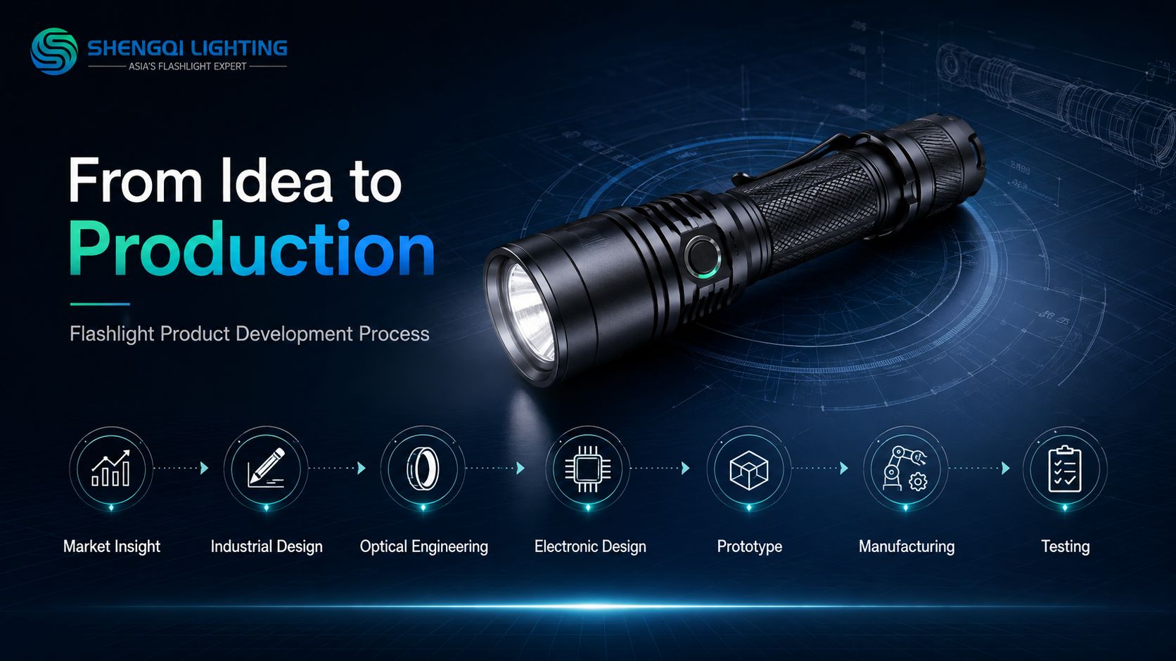

How does flashlight ODM product development work?
Flashlight ODM product development turns a market requirement into a manufacturable product by connecting product definition, industrial design, optics, electronics, battery architecture, mechanical and thermal engineering, DFM, prototype verification, pilot production, quality control and testing. A measurable product brief defines the application, output roles, beam, battery, dimensions, environmental targets, user interface, packaging and commercial boundaries. Engineering then resolves subsystem conflicts before a prototype is approved. A documented design freeze connects drawings, BOM revisions and test evidence to the approved configuration. A pilot build tests the process, while IQC / IPQC / FQC and selected testing support production release and mass-production consistency. Engineering change control then manages later component or specification changes. The exact workflow varies by project.
What should a B2B buyer verify when evaluating a flashlight ODM partner?
A B2B buyer should verify whether the ODM can connect engineering decisions to traceable drawings, specifications, prototypes, test records, production controls and change-management records. Review how optics, electronics, mechanics and battery architecture are defined, how DFM is completed before release, what each prototype stage is expected to verify, and how production quality is controlled. Buyers should also ask which model revision, battery and operating condition support each important test result. Revision control should connect the approved sample with the production BOM and packaging. Factory equipment alone is not enough evidence of a controlled product-development process.
Market Insight Must Become an Engineering Brief
Distributor feedback, customer inquiries, sales data, product reviews, competitor architecture, channel requirements and target pricing can reveal an opportunity. They are not yet engineering specifications. “We need a 2,000-lumen flashlight” still leaves the task distance, beam, battery, dimensions, runtime expectation, thermal behavior, IP target, interface and packaging undefined.
A useful product brief converts those inputs into measurable requirements. SHENGQI's flashlight design and development services can support the transition from an initial concept toward an engineering definition.
Separate Must-Have Requirements From Nice-to-Have Features
Core application, battery architecture, size, output role, environmental target and compliance boundary.
Output levels, beam, runtime target, thermal behavior, impact, IP and charging where applicable.
Sensors, magnets, side lights, red or UV functions, clips, displays and custom UI logic.
Every added feature can affect PCB space, battery capacity, heat, sealing, switch logic, assembly, cost, testing and failure modes. Feature count is not the same as product value.
Industrial Design Defines More Than Appearance
Industrial design should resolve grip, proportions, switch location, pocket carry, anti-roll geometry, head and body diameter, battery access, clip position and brand language. CMF—Color, Material and Finish—then connects material choice, anodized finish, texture and logo treatment with the intended product identity.
A visually attractive flashlight can still fail if the grip blocks heat dissipation, the clip interferes with controls, the battery cannot be serviced or the geometry is difficult to machine. ID must remain connected to engineering reality.
Optical Engineering Starts With the Task, Not the LED Name
LED, reflector or TIR optic, lens, emitter position, beam angle, hotspot, spill, luminous intensity and total output interact. A maintenance light may need a wide task beam, while another product may need a balanced general-purpose beam or longer directional illumination.
Lumens alone do not define beam usefulness. SHENGQI lists Optical Engineering, reflector and TIR development, beam evaluation and luminous-performance testing among its relevant capabilities.
LED Selection Is a System Decision
LED selection must be evaluated with voltage, current, efficiency, CCT, CRI where relevant, optics, thermal load, driver, battery, output target and body size. A higher-output LED may create new electrical, thermal and runtime constraints.
Electronic Design Turns Features Into Controlled Behavior
Electronic Design and PCB Layout translate product functions into current regulation, voltage range, battery protection, mode logic, switch input, low-voltage behavior and charging, temperature or indicator functions when the project requires them.
User-interface features should be designed into the electronics architecture before the housing is frozen.
Battery Architecture Changes the Entire Product
AAA, AA, 14500, 16340, 18650, 21700 and integrated lithium platforms create different body dimensions, current capability, runtime, charging, transport, serviceability, weight and thermal constraints. Rechargeable is not always better, replaceable is not always better, and similar cell dimensions do not establish interchangeability. Existing portable-lighting product platforms illustrate how different architectures serve different product briefs.
Mechanical Engineering Connects Every Subsystem
Body, head, tail, battery compartment, threads, switch, clip, magnet, charging cover, O-ring, lens seat, reflector seat, PCB location and thermal path all need physical space and an assembly sequence.
A feature that appears simple in a rendering can create tolerance conflicts, weak wall thickness, difficult machining, assembly interference, sealing risk or serviceability problems.
Thermal Design Must Be Resolved Before High Output Is Approved
High-output design should consider LED heat generation, PCB temperature, thermal path, aluminum structure, surface area, driver behavior, battery temperature, step-down strategy and user-touch surfaces. Maximum output should be evaluated together with temperature and output-over-time behavior.
Tolerance Problems Often Appear Only After Parts Meet
A lens, reflector, LED board, head, tube, switch, O-ring and tailcap can each meet its individual drawing and still create an assembly problem when their tolerances accumulate. Buyers should ask which dimensions are critical-to-fit, critical-to-sealing and critical-to-optical alignment.
DFM Is the Bridge Between a Good Design and a Buildable Product
Design for Manufacturing (DFM) checks whether the product can be machined, assembled, inspected, sealed, tested, repeated and serviced where required while remaining within the project's cost structure.
A project-specific DFM review can examine wall thickness, machining and tool access, tolerances, threads, undercuts, part count, assembly direction, fastening, soldering access, PCB installation, O-ring compression, component availability and test access. DFM is not about lowering design standards; it is about making the intended design manufacturable before tooling or production geometry is frozen.
A Prototype Proves a Concept, Not Mass Production
An appearance prototype can review proportions, CMF and hand feel. A functional prototype can review optics, electronics, switch logic, battery fit and basic thermal behavior. An engineering sample can move closer to intended materials, manufacturing architecture, assembly, sealing and performance.
SHENGQI lists rapid prototyping and CNC machining among its current capabilities. A successful prototype still does not prove mass-production consistency.
Flashlight Prototype Verification Matrix
| Engineering Area | What the Prototype Should Verify | Evidence | Typical Risk | Design Decision |
|---|---|---|---|---|
| Industrial Design | Grip and proportions | Sample review | Poor handling | Geometry |
| Optical Performance | Beam and output role | Optical record | Wrong beam | Optics |
| Electronics | Modes and regulation | Functional test | Unstable behavior | PCB / logic |
| Battery | Fit and electrical match | Battery test | Mismatch | Platform |
| Thermal Behavior | Heat path | Temperature record | Excess heat | Output / structure |
| Mechanical Fit | Assembly and tolerance | Fit review | Interference | Dimensions |
| Waterproof Structure | Seal concept | Applicable test | Leak path | Seal design |
| Switch / UI | Control logic | Functional review | User error | UI |
| Drop / Mechanical Durability | Structural retention | Project test | Damage | Structure |
| Packaging Interface | Fit and protection | Pack review | Movement | Packaging |
Design Freeze Should Be a Documented Decision
Before formal production preparation, the project should identify the approved model, drawing revision, BOM, LED, optics, PCB, firmware where applicable, battery, materials, finish, O-rings, dimensions and packaging configuration. Freeze does not mean nothing can ever change; it means later changes become controlled engineering changes.
Pilot Production Tests the Process, Not Just the Product
A pilot build can reveal assembly difficulty, component variation, tooling issues, fastening problems, soldering issues, sealing variation, cosmetic variation, test bottlenecks and packaging problems. Pilot quantity and validation scope are project-specific.
Quality Control Must Follow the Product Through Production
IQC — Incoming Quality Control: project plans may check LEDs, batteries, aluminum components, PCBs, optics, switches and packaging materials.
IPQC — In-Process Quality Control: project plans may check assembly, soldering, alignment, switch function, appearance, sealing components and intermediate performance.
FQC — Final Quality Control: project plans may check final function, appearance, identity, packaging and selected performance items. Exact sampling methods and acceptance limits should be defined for the final SKU.
Manufacturing Capability Matters When It Is Connected to Engineering
SHENGQI's current machining and production capabilities include 75 CNC machines, with 5-axis CNC listed among manufacturing capabilities, one fully automated SMT line, two welding lines and eleven dust-free assembly lines. The manufacturing workflow also lists CNC machining, threading, drilling, anodizing, engraving, assembly and packaging.
This does not mean all 75 CNC machines are 5-axis, every project requires 5-axis machining, or that every manufacturing process is performed identically for every product.
Electronic Assembly Must Match the Approved PCB
The value of SMT is not automation alone. Component placement, PCB revision control, approved component identity, repeatable electronic assembly and appropriate inspection must remain connected to the released electronic design.
Testing Should Close the Engineering Loop
SHENGQI's flashlight testing and quality-control capabilities include integrating-sphere testing, discharge-time testing, water-resistance testing, temperature assessment, battery testing, button testing and impact-related testing.
Each test should answer a design question: Does output match the optical target? How does output change over time? Does the assembled enclosure meet the applicable water-resistance target? Does the battery behave as expected? Does the control remain functional under the defined test cycle?
A Testing Capability Is Not the Same as a Model-Specific Result
Equipment photographs demonstrate capability. Traceable records demonstrate the result. Buyers should ask which model, revision, battery, mode and conditions were tested, what result was recorded, what acceptance criterion applied and what report identifies the sample.
Seven Common Conflicts ODM Engineering Must Resolve
A smaller body reduces thermal mass and internal space. Higher output can increase current and heat. The project must balance size, temperature and output duration.
More energy usually requires more battery volume or lower output. Weight, runtime target and battery architecture should be resolved together.
Serviceable compartments create interfaces that must still seal correctly. Access and ingress protection require joint mechanical review.
More modes can increase switch complexity and user error. The interface should match the actual workflow rather than maximize feature count.
Magnet size, holding direction, steel structure and nearby components can affect packaging and mechanical layout. Magnetic performance needs a defined use case.
Complex surfaces, tighter cosmetic standards and extra processes can add cost and inspection requirements. CMF should be reviewed with the target price architecture.
Reducing validation can leave unresolved engineering risk. Project timing should define which risks must be closed before release.
ODM engineering is often trade-off management.
Market Request to Engineering Specification
| Market Request | Engineering Question | Subsystem | Verification Needed | Risk if Undefined |
|---|---|---|---|---|
| Make it brighter | At what distance, duration, body size and battery? | Optical / thermal | Output over time | Heat / runtime |
| Make it smaller | Which components can shrink? | Mechanical | Fit review | Interference |
| Make it last longer | At which mode and endpoint? | Battery / electronics | Discharge test | Unrealistic runtime |
| Make it waterproof | Which exposure target? | Mechanical | Applicable water test | Seal failure |
| Add a magnet | Where and on what surface? | Mechanical | Mounting review | Poor holding |
| Add red / UV / side light | What task and mode logic? | Optics / PCB | Functional test | UI complexity |
| Use a common battery | Which approved electrical specification? | Battery | Compatibility test | Mismatch |
| Make it premium | Which material, finish and tactile targets? | ID / CMF | Sample approval | Subjective brief |
| Reduce cost | Which function cannot change? | Cross-system | DFM / BOM review | Performance loss |
| Launch quickly | Which validation gates remain mandatory? | Project | Risk review | Unresolved defects |
Mass Production Is a Controlled Ramp, Not a Copy-Paste Step
Incoming materials, fixtures, tooling, operator instructions, assembly sequence, intermediate checks, product tests, cosmetic standards, packaging and revision control still matter after a prototype is approved. The goal is to reproduce the approved product repeatedly, not merely reproduce its appearance.
A Small Component Change Can Change the Product
Changes to an LED supplier or bin, battery, PCB, MOSFET, charging IC, switch, reflector, TIR optic, lens, O-ring, spring, magnet, adhesive, aluminum material, finish or packaging may require review. The impact depends on what the component influences: a battery can affect output, runtime, charging or transport documents; an O-ring can affect sealing; an LED can affect output, beam, CCT and thermal load.
The Approved Sample Needs Documents Behind It
The physical sample should connect to a model number, BOM revision, drawing revision, PCB revision, battery, optics, finish, packaging revision and approved test results. A sample without revision records is difficult to use as a production-control reference.
Ten Questions to Ask a Flashlight ODM Before Starting Development
Ask how application, output, battery, dimensions and environmental targets will be defined.
Clarify ID, optics, electronics, mechanics and battery responsibilities.
Identify drawings, components, UI, materials and test targets.
Ask how machining, assembly, sealing, tolerances and test access will be considered.
Separate appearance, functional and production-oriented questions.
Review thermal, runtime, optical, water-resistance and mechanical evidence.
Look for revision-controlled BOMs, drawings and approved results.
The process should capture assembly and production risks before release.
The exact inspection plan should match the final SKU and project risk.
Ask how affected drawings, tests, components and packaging are reviewed.
B2B buyers should evaluate continuity between specification, engineering, prototype, validation and production—not factory photographs alone.
Flashlight ODM Engineering Evidence Chain
| Development Stage | Main Question | Expected Output | Evidence | Approval Owner |
|---|---|---|---|---|
| Market Requirement | What problem? | Requirement set | Buyer input | Buyer |
| Product Brief | What is measurable? | Defined targets | Specification | Joint Review |
| ID / CMF | How should it look and handle? | Design direction | Drawings / samples | Joint Review |
| Optical Design | What beam? | Optical architecture | Optical data | ODM Engineering |
| Electronic / Battery Design | How will it operate? | PCB / battery architecture | Schematics / specs | ODM Engineering |
| Mechanical / Thermal Design | Can systems fit and manage heat? | Integrated structure | Drawings | ODM Engineering |
| DFM | Can it be built repeatedly? | Production-ready review | Project review | Joint Review |
| Prototype | Does the concept work? | Physical sample | Prototype record | Joint Review |
| Engineering Verification | Does performance match targets? | Verified configuration | Test records | Quality |
| Design Freeze | What revision is approved? | Frozen configuration | BOM / drawings | Joint Review |
| Pilot Build | Can the process reproduce it? | Production feedback | Pilot records | Project-Specific |
| Mass-Production Release | Are controls ready? | Released production | QC / production records | Quality |
| Engineering Change Control | What changed and what is affected? | Controlled revision | Change records | Joint Review |
What “Integrated R&D and Manufacturing” Should Mean in Practice
An integrated ODM workflow should connect customer requirement, industrial design, optics, electronics, mechanics, battery, prototype, manufacturing process, test method, quality control, packaging and change control.
Integration is traceability between engineering decisions and production evidence: Requirement → Drawing / Specification → Sample → Test Record → Production Revision.
How SHENGQI LIGHTING Connects Design, Engineering and Production
SHENGQI combines Industrial Design, Optical Engineering, Electronic Design, PCB Layout and Packaging Design with machining, SMT, assembly, production quality control and product-testing capabilities. Its current website lists 75 CNC machines, one fully automated SMT line and eleven dust-free assembly lines among relevant manufacturing resources.
SHENGQI LIGHTING has manufacturing roots dating back to 1981, while the current company was formally established in 2008. It operates under an ISO9001 quality management system, which supports structured process control while product-specific claims still require product-specific evidence.
SHENGQI's ODM value should be evaluated by how design, engineering, prototype, manufacturing and verification can be connected within one product-development workflow—not by assuming every capability is applied identically to every project.
Frequently Asked Questions
1. What is the flashlight product development process?
The process converts a market requirement into a product brief, then resolves ID, optics, electronics, battery architecture and mechanics before prototype development. Prototype testing checks form, beam, electronics, thermal behavior and assembly. The approved configuration is then documented before pilot and production preparation. The exact stages vary by project, but the key principle is continuity between requirements, engineering decisions, testing and production evidence.
2. What is the difference between OEM and ODM flashlight development?
OEM often begins from a more defined buyer specification or existing product platform, while ODM generally involves deeper participation in product definition and engineering. In practice, projects can overlap: an OEM project may still require engineering changes, while an ODM project may begin from a mature platform. Commercial usage of OEM and ODM terminology varies by supplier and project, so buyers should define responsibilities rather than rely on the label alone.
3. Why is DFM important before flashlight mass production?
DFM checks manufacturability before production geometry is released. It can reveal problems involving tolerances, machining access, assembly direction, sealing, part count, fastening and test access. It also helps the team understand how design decisions affect production cost and repeatability. DFM does not replace product testing; it helps ensure that the intended product can be manufactured and inspected consistently using the selected production architecture.
4. What should a flashlight prototype verify?
Depending on the prototype stage, it should verify form, optical output and beam behavior, electronics, battery fit, thermal behavior, mechanical fit, switch and user-interface logic, and sealing where relevant. Later engineering samples may also review intended materials and assembly architecture. A prototype should answer defined engineering questions; a visually successful sample alone does not prove that the same design can be repeated reliably in mass production.
5. Why does battery selection need to happen early in product development?
Battery architecture affects body size, available current, runtime, charging design, thermal behavior, transport documentation, weight and user serviceability. It also influences spring contacts, protection, charging circuits and enclosure geometry. Selecting the battery late can force changes across multiple subsystems. Buyers should define the intended battery workflow early and verify the exact approved chemistry, voltage and configuration rather than assuming similarly sized cells are interchangeable.
6. How do IQC, IPQC and FQC support flashlight production?
IQC focuses on incoming materials and components before they enter production. IPQC focuses on in-process assembly, soldering, alignment, sealing parts, functional checks and other project-defined production controls. FQC focuses on the completed product, including final function, appearance, identity, packaging and selected performance items. The exact sampling method and acceptance criteria should be defined for the project rather than assumed to be universal.
7. Does owning CNC machines and testing equipment prove strong ODM capability?
No. Equipment demonstrates capacity to perform manufacturing or testing work, but a controlled ODM process also requires specification management, revision control, engineering coordination, prototype verification, traceable test records and production evidence. Buyers should ask how the approved design is connected to the BOM, drawings, test results and production revision. Factory equipment is valuable when it supports a controlled engineering workflow rather than standing alone as a marketing claim.
8. What should buyers prepare before starting a custom flashlight ODM project?
Prepare the target user, application, sales channel, desired dimensions, output roles, beam requirement, battery preference, IP target, runtime target, required features, target compliance market, packaging needs and commercial constraints. Exact answers are not required for every field at the beginning, but unresolved assumptions should be identified. A clearer brief helps engineering teams compare trade-offs and prevents vague requests such as “brighter,” “smaller” or “more premium” from becoming uncontrolled design changes.
Connect the Product Brief to Engineering and Production Evidence
Flashlight brands, outdoor and EDC companies, industrial-tool businesses, product managers, engineering teams, sourcing managers and private-label buyers can discuss product briefs, Industrial Design, optical engineering, electronics, battery architecture, mechanical integration, DFM, prototype validation, production planning, testing and packaging development.
Contact SHENGQI LIGHTING for an OEM/ODM technical evaluation at sales@shengqilight.com.