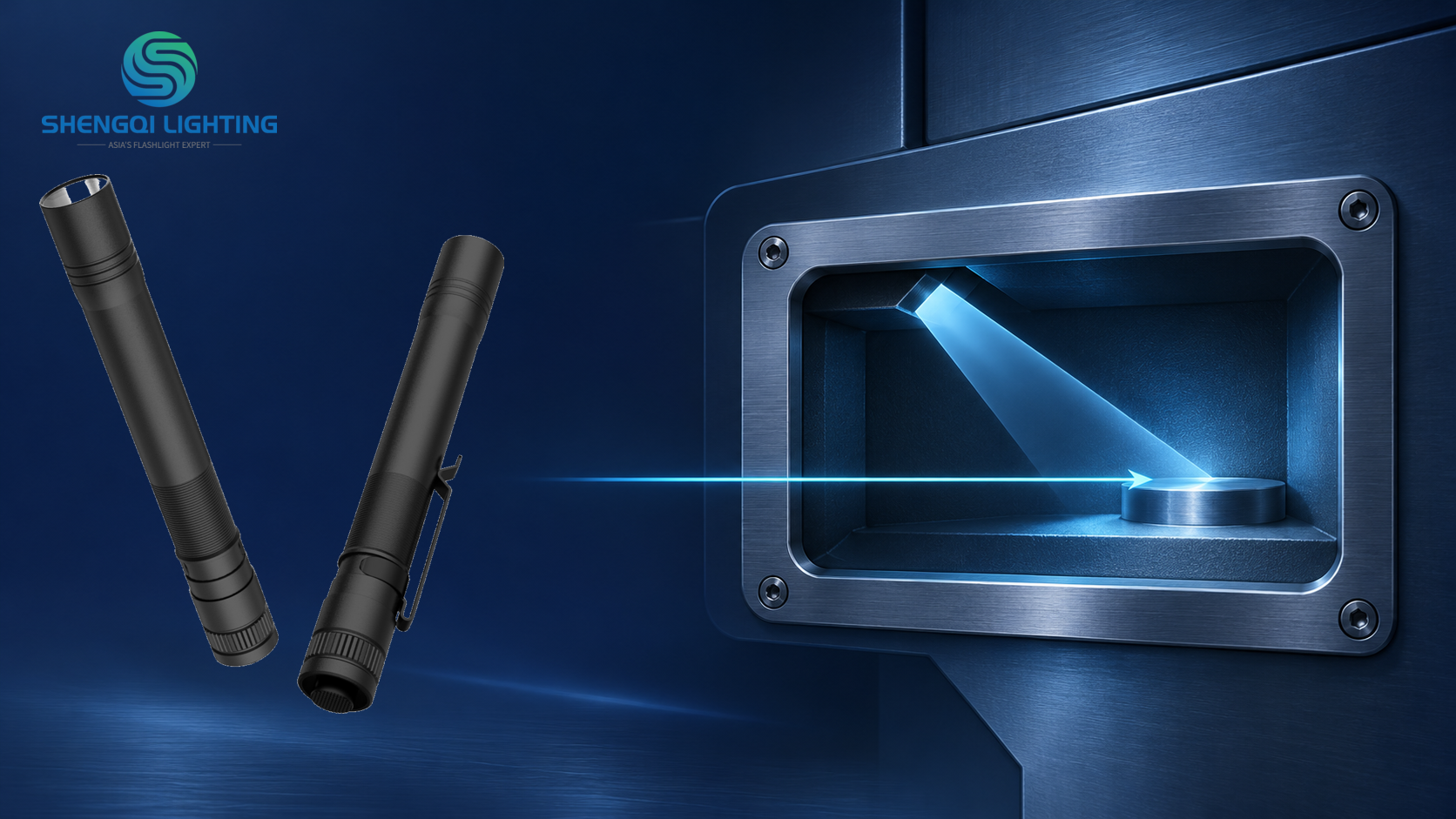
A technician may be able to insert a slim light through an equipment opening and still fail to see the target clearly. The light body fits, but the hand blocks part of the viewing path; a tool then enters the same space and creates another shadow. In this situation, the useful choice is not simply a penlight or a work light. It is the lighting arrangement whose light window, target, viewing direction, and hand or tool path can work together.
For inspection, an end beam is worth considering when the useful light path can follow the length of the light into the target area. A side light is worth comparing when a nearby task area needs coverage from a different placement position. Neither layout wins by name alone. The right decision comes from checking where the target is, where light can leave the product, where the user must look, and what changes after hands and tools enter the task.
In this article:
The four positions to check · Three inspection situations · End beam and side light comparison · Sample check method · How to describe the task
Start With the Light Window, Not the Product Label
Penlight describes a pen-shaped product form. Work light describes a task-lighting use. These descriptions can overlap. A pen-shaped product may use a side light, and another product may combine an end beam with a side-facing light source. For that reason, a useful penlight vs work light decision is usually a comparison of lighting layouts, not a claim that two rigid product categories are opposites.
This article compares two common configurations: a slim light that mainly directs light from its end, and a task-light configuration that mainly directs light from its side toward a nearby work area. End and side describe where light leaves the product; spot and flood describe how that light is distributed. One description does not prove the other.
Likewise, a side-facing light is not automatically a particular LED package, an end beam is not automatically a narrow long-distance beam, and a pocket clip is not automatically a stable hands-free mounting solution. If a product has two light sources, its specification and sample behavior must still confirm how each source is selected, positioned, and used.
Check Four Positions at the Same Time
Inspection lighting becomes more reliable when a user checks four physical positions together. A brighter light cannot automatically correct a blocked light path, a poor viewing angle, or a tool that occupies the only available space.
1. The target
Define what must be seen: a recessed marking, a component edge, several neighboring parts, or a changing operation. The target determines whether the task needs a narrow direction, broader nearby coverage, or a different light position.
2. The light window
Ask where the emitting surface sits after the light is placed. A housing edge, the opening itself, or a nearby component can block the useful direction even when the product body fits.
3. The observer
Light reaching the target does not guarantee a clear sightline. Check the view from the operator’s normal position, including whether reflection, an opening edge, or the light body interferes with the detail being inspected.
4. Hands and tools
The situation changes when a hand steadies a part or a tool begins to move. Recheck the light window, the light path, and the viewing path after the working posture—not only during a static demonstration.
Workplace-lighting guidance similarly emphasizes the task, the surface, the work area, and the normal working position when lighting is assessed. Portable inspection lights add the practical question of where the product itself can be placed. Read the general lighting ergonomics reference.
Three Inspection Situations That Change the Decision
Viewing a recessed target through a small opening
A slim pen inspection light may fit through or near an opening, but that resolves only one part of the task. With an end beam, check whether the end window can remain exposed and point toward the target without the user’s fingers, the opening edge, or the viewing posture blocking the route. A side light may help only when its emitting surface can sit in a useful position and face the target area. If the direct path is blocked, simply increasing output does not guarantee that the target will become visible.
Reading markings across a nearby area
When the task is to read several labels, check neighboring parts, or understand their relative position, the useful question is how the target area is covered from the available light position. A side-light task configuration can offer a practical option for broad nearby coverage, but side placement alone does not prove uniformity or freedom from glare. An end beam may also cover the task well when its actual beam pattern and working distance suit the area. On reflective material, evaluate the view from the normal observation position; moving the light angle can be more useful than adding output.
Moving from observation to two-handed work
A product can appear suitable while the operator only looks at the target. Once both hands and a tool enter, a previously clear path can become a shadow or a blocked line of sight. A clip, stand, magnet, or other retention method must be evaluated for the actual orientation and available space. If the light can be fixed but occupies the tool path, the arrangement still needs to change. A dual-light layout can add another lighting option, but it does not automatically solve every shadow or confirm that both sources can operate together.
End Beam vs Side Light: Compare the Task Conditions
| Task condition | End-beam layout: confirm | Side-light layout: confirm | Common limitation | Sample judgment method |
|---|---|---|---|---|
| Recessed target behind a small opening | Whether the end window can point into the useful path after the body is positioned. | Whether the side-emitting surface is exposed, faces the target, and is not hidden by the opening edge. | A fitting body can still leave no usable light path or sightline. | Place the sample at the intended position and inspect the target from the normal viewing direction. |
| Labels or adjacent components across one area | Actual coverage at the task distance, rather than assuming the end beam is only a small point. | Coverage, angle, and whether the window can be placed beside the task area. | A bright appearance at the source does not prove useful distribution at the target. | Verify that all required labels and relationships can be read from the working position. |
| Reflective or glossy target surface | Whether the beam angle creates reflected glare in the operator’s line of sight. | Whether a side position improves the viewing angle or creates another reflection. | More output can make reflection more distracting instead of revealing detail. | Keep the viewing position fixed, then adjust the sample position or angle and record the clearer arrangement. |
| Continuous work with hands and tools in the area | Whether the hand-held direction remains useful after the operator changes grip or begins work. | Whether the light can stay aimed without consuming the tool path or obstructing the hands. | A fixed position may be stable but still be in the way of the operation. | Repeat the check after the operator’s hands and normal tools are in place. |
Prioritize an end beam when the available placement lets the light follow a practical direction toward a small or recessed target and the end window remains unobstructed.
Compare a side-light configuration when the task needs a nearby area illuminated from a location that is not aligned with the product’s length, or when the light needs to stay beside the operator’s work.
Evaluate dual sources when two genuinely different task directions must be checked, but confirm each source’s operation and placement separately. Do not assume simultaneous operation or add maximum-output figures across channels.
Change position first when the sample produces glare, a hard shadow, or a blocked view from the normal observation direction. A better angle may solve the actual problem without changing the lighting category.
Run a Focused Sample Check Before Selecting a Layout
Use a safe, stationary sample setup or a task environment that has already met its applicable safety conditions. This is an observation method for inspection lighting; it is not guidance for equipment repair, energized work, entry into confined spaces, or a substitute for a formal safety assessment.
- State the visible target. Record the exact character, edge, part relationship, or operation that must be observed. “Looks bright enough” is not a sufficient task definition.
- Record the real space. Note the opening, target location, practical light positions, normal observation position, and working distance. Leave a field blank if the information is not yet known.
- Arrange one candidate layout at a time. Record the product orientation, selected mode, and light-window position. The purpose is task fit, not a claim that one sample has higher technical efficiency than another.
- Observe before and after hands and tools enter. Compare the initial view with the working posture. Note whether the light path, viewing path, or tool clearance changes.
- Check glare and shadow from the real viewing direction. If adjustment helps, write down what moved and why the view improved.
- Decide against the original target. The result can be suitable, suitable after repositioning, better served by another layout, or still unknown. Unknown conditions should remain open items, not be marked as passed.
| Target and task | Opening / target position | Working distance | Light position, direction, and mode | What changes after hands / tools enter? | Open question |
|---|---|---|---|---|---|
| [What must be identified?] | [Describe available access and target location] | [Record if known] | [End or side window, orientation, mode] | [Shadow, blockage, clearance, or no change] | [What still needs confirmation?] |
Turn the Observation Into a Clear Product Requirement
“Need a bright pen work light for inspection” is not enough information to define a useful lighting layout. It does not describe the target, the available light position, where the user looks, or what space hands and tools need. A stronger request gives the development discussion a visible problem to solve.
Requirement-writing template
“The inspection target is [marking / edge / part relationship / process]. It sits [describe its position relative to the opening or surrounding parts]. The light can be placed [available locations and directions], while the operator normally views from [viewing direction]. The task [does / does not] require both hands. We can provide [photos, dimensions, or a simple sketch]. Known requirements are [known items]; the lighting layout or remaining conditions to discuss are [open items].”
This type of information allows a conversation about the light window, body space, beam direction, and potential retention approach without assuming that a familiar product name already answers the task.
Use Product Categories as Starting Points, Not Final Answers
For a slim, close-access direction, browse SHENGQI LIGHTING Pen Lights. For a task-area or placement-oriented direction, browse Tooling and Work Lights. The categories help identify product directions, but individual suitability still depends on the specific model, its actual light-window layout, and the user’s task arrangement.
For a broader framework covering form factor, distance, beam character, and hands-free work, see How to Choose Portable Lighting for Industrial Inspection and Maintenance. That guide addresses category-level selection; this article focuses on how the physical placement of the light changes the result inside a restricted task space.
The technology in a well-defined inspection light is visible in the coordination of its emitting surface, body shape, possible adjustment, and the user’s real movement—not in a feature list alone. SHENGQI LIGHTING’s design and development services describe industrial design, optical engineering, electronic design, and prototyping capabilities. A specific platform should still be evaluated against the actual target area and operating conditions before a fit is confirmed.
Frequently Asked Questions
Does a pen work light always have a side light?
No. “Pen work light” can describe a slim product used for work, but it does not prove the position of its light window. Confirm the product’s actual lighting layout rather than relying on the name.
Is side light always flood lighting?
No. Side and end identify where light exits the product. Flood and spot describe beam distribution. A sample or product specification is needed to understand the useful coverage at the intended working distance.
Why can a light body pass through an opening while the target remains unclear?
The opening may accept the body but still obstruct the light window, the direct light path, or the observer’s view. Hand position and nearby components can create additional blockage after the light is inserted.
Does a pocket clip create hands-free inspection lighting?
Not by itself. A clip may offer another carrying or attachment option, but the actual attachment point, angle, stability, light direction, and tool clearance must be checked in the intended task.
Will an end beam plus a side light eliminate hand shadows?
Not automatically. Two sources can provide two placement options, but each light window can still be blocked and each path can still create reflection or shadow. Test the complete working posture before treating a dual-source layout as the solution.
Discuss Your Inspection Lighting Layout
Share photos of the target area, the opening and working distance, the normal viewing direction, and whether the task requires both hands. SHENGQI LIGHTING can then discuss an appropriate platform or design direction based on the specific evaluation conditions.