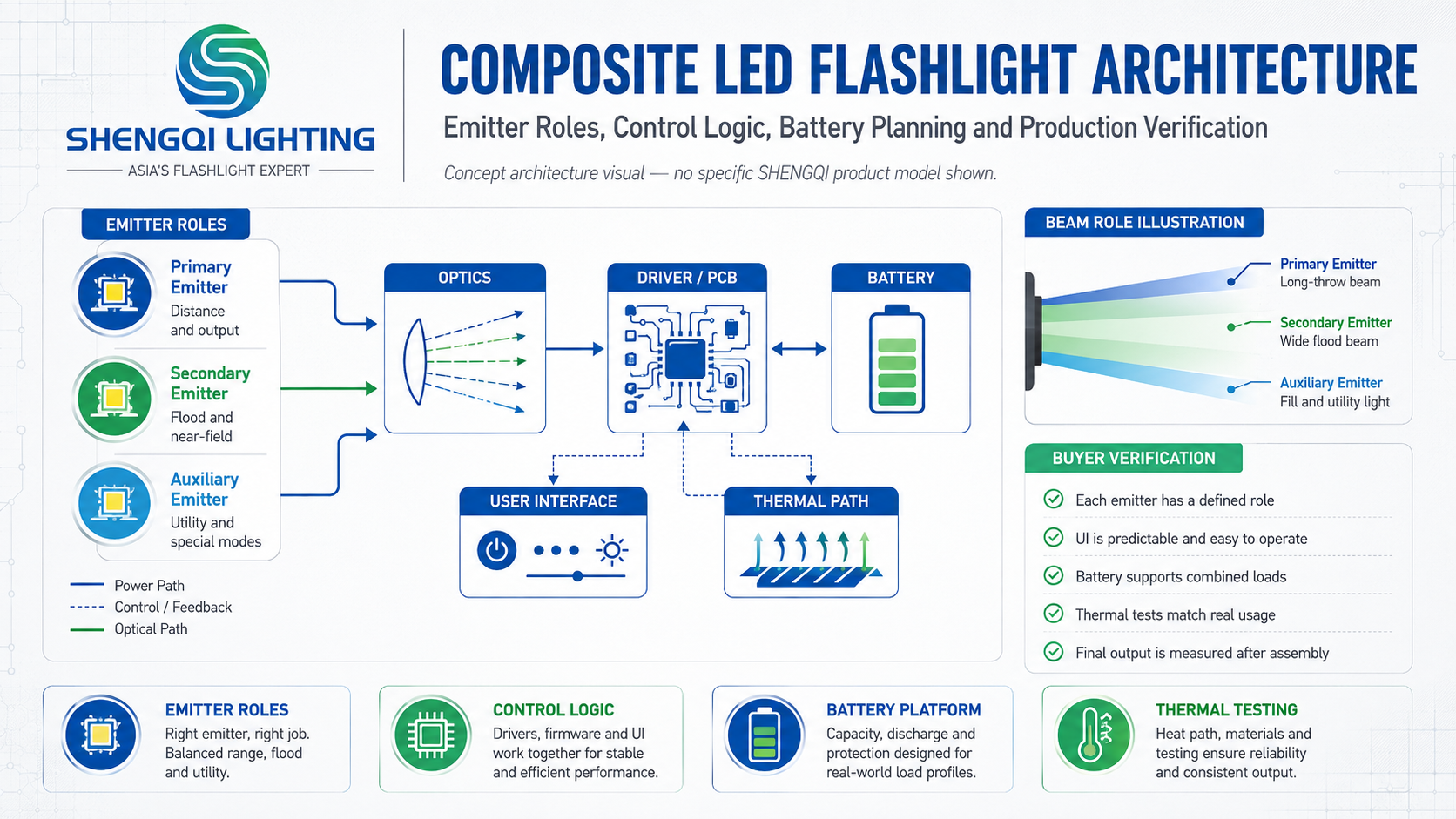

What Is a Composite LED Flashlight?
A Tactical Flashlight with Composite LED architecture is best understood as a rugged handheld portable-light concept in which more than one light-emitting function, emitter or die is integrated into the same product system. The important word is system. Emitter count by itself says very little about beam quality, runtime, usability or durability.
The design might support a directional primary beam plus another task-light function, different beam widths, separate white-light characteristics or a project-specific auxiliary source. What matters is why each emitter exists and how the optics, electronics, controls, battery and enclosure support those roles.
Brands developing rugged handheld products can review existing tactical flashlight platforms for general directional-light architecture without treating those models as existing Composite LED products.
What Does “Composite LED” Mean in a Flashlight?
“Composite LED” should not be treated as one universal ANSI, IEC or other standardized flashlight architecture. In product-development discussions, the term may be used broadly to describe a system that integrates more than one light-emitting function, emitter or die.
Depending on the project, that could involve multiple discrete LEDs, a multi-die package, different white-light emitters, white plus colored emitters, separate main and auxiliary light sources, or another project-specific multi-emitter arrangement.
The exact architecture must be defined in the product specification. A buyer should never assume that “composite LED” automatically means COB, RGBW, dual-chip, UV, red light or any other specific configuration.
Start With the Lighting Tasks, Not the Number of LEDs
Why does the product need multiple light sources? One emitter may be intended for directional handheld lighting while another supports broader close-range illumination. A lower-output auxiliary source may serve a separate task. A colored or wavelength-specific source may be justified only when the application requires it.
Before emitter count is discussed, define the main use case, primary beam, secondary beam, typical working distance, low-light requirement, any specialized color requirement, control workflow, battery target and body-size envelope.
More LEDs do not automatically create more product value. If an emitter has no clearly defined job, it may simply add cost, UI complexity, heat and assembly work.
Multiple Emitters Create More Optical Freedom—and More Engineering Work
A multi-emitter architecture can separate beam roles, support different beam angles, cover different output ranges or provide independent front and side illumination. Those options are useful only when the complete design supports them.
Each additional source can require another driver channel, optical window, PCB area, thermal path, sealing interface, control state and assembly step. Depending on the structure, it may also affect machining, wiring, brackets, lenses and alignment.
Every additional emitter should have a defined task. Two, three or four emitters do not by themselves prove that a flashlight is brighter, more durable, more premium or better engineered.
Different Emitters Need Clearly Defined Beam Roles
A primary directional beam may prioritize a controlled hotspot, usable intensity and surrounding spill. A secondary wide beam may be intended for close task areas and broader local visibility. If the project requires an auxiliary colored or specialized source, its purpose should be defined separately.
Red, UV or other wavelengths are possible architecture examples, not default features. Red light may support lower-disturbance task lighting in some workflows. UV may support inspection applications only when the relevant fluorescence response and wavelength requirement are clearly defined.
Front-plus-side illumination is another common multi-source concept. Existing portable task-lighting architectures can provide structural references for this type of product planning without being relabeled as Composite LED tactical flashlights.
The optical system should prevent the final product from becoming a collection of unrelated beams.
Total Lumens Do Not Explain How a Multi-Emitter Flashlight Performs
When several LEDs are present, a single “total lumens” number can hide important operating details. Are all emitters active at the same time? Does the figure describe only the primary source? Which mode was measured? Is it initial output or sustained output?
Individual LED ratings should not simply be added together to create a finished-product claim. Driver current, simultaneous operating logic, optical losses, battery voltage and thermal regulation all affect real system performance.
System output should be measured on the final assembled product. Beam intensity should also be evaluated separately from total luminous output because the same lumen figure can produce different beam behavior depending on the optical system.
Colored or Specialized Emitters Need a Real Use Case
A multi-emitter product can use different colors, white-light characteristics or wavelengths, but those choices should come from the application rather than feature count.
Different white emitters may be selected for different beam or visual requirements. CCT and CRI targets should follow the task; there is no universal “tactical” CCT or automatically superior CRI target.
Specialized wavelengths need even tighter definitions. A UV source should not be promoted as detecting every stain, contaminant, biological material or authenticity marker. The relevant material response, wavelength and inspection method must be defined for the intended application.
Multi-Emitter Flashlights Need a User Interface That Explains the Product
Multiple light sources can create a control problem faster than an optical problem. Separate switches, grouped mode logic, direct access, long press, double click, source selection, lockout and mode memory are all possible design options.
The product brief should define first activation, primary-beam access, secondary-beam access, specialized-source access and accidental activation. If a strobe mode is included, buyers should decide whether it needs direct access or should remain separated from normal task modes.
A multifunction flashlight should reduce cognitive load, not advertise feature count through complicated controls. Users should not have to cycle through a long sequence of unrelated modes simply to select another emitter.
Battery Architecture Must Support the Worst Real Operating Combination
Some products operate one emitter at a time. Others may allow the main source and side light to run together, or combine multiple sources in selected modes. Those combinations can create very different electrical loads.
Buyers should define peak electrical demand, permitted simultaneous operation, runtime targets, charging workflow, serviceability, body size and weight before the battery is selected. There is no universal answer that makes a particular cylindrical cell or integrated battery automatically better.
Battery capacity alone does not define maximum output, sustained output, runtime or thermal behavior. Voltage, current capability, driver design, LED efficiency, operating mode and thermal regulation all contribute to the final result.
More Emitters Create More Thermal Scenarios
Thermal verification should not be limited to an unrealistic “everything on maximum” condition. The product may spend more time with the primary emitter on high, a secondary source on high, two emitters operating together or a medium mode running for an extended period.
The thermal path can involve LED boards, PCB structure, body material, contact surfaces, driver components, battery and enclosure geometry. If thermal step-down logic is used, its behavior also becomes part of the user experience.
Thermal testing should follow the real operating modes defined in the product brief. No fixed temperature, step-down point or sustained-output value should be assumed until the final architecture is tested.
Every Extra Emitter Needs Physical Space, Optical Space and Assembly Control
An additional LED may require its own optical window, reflector, TIR optic, lens, gasket, PCB area, wiring, bracket, thermal contact and control path. That can affect body size, wall thickness, machining, sealing, assembly and alignment.
Each additional window, switch or opening also becomes another interface that must be considered in the enclosure design. This does not mean a multi-emitter flashlight is inherently less water-resistant; it means the project's final ingress-protection target has to be engineered around the complete enclosure.
Multi-emitter design is therefore a mechanical architecture problem as much as an LED-selection problem. Brands can review broader SHENGQI portable lighting products for general enclosure and optical-layout references without implying that an existing model matches this concept.
Reliability Must Be Evaluated as a System, Not Emitter by Emitter
An LED can function correctly, the switch can pass an individual test and the battery can perform normally while the complete product still shows source-selection errors, excessive heat, unstable low-voltage behavior, inconsistent beam alignment or unexpected shutdown.
Failure behavior should also be defined. If a secondary emitter fails, should the primary source remain functional? Does one driver control all sources? How does low-voltage protection affect each function? Those answers depend on the approved electrical architecture.
PCB and Driver Architecture Should Follow the Approved Emitter Combination
Multi-emitter products may require multiple driver channels, controlled current, source switching, battery monitoring, thermal logic and UI control. The electronic architecture should be defined around the approved emitter combination and user interface rather than added after the optical layout is finished.
Prototype validation can use broader portable-light testing capabilities, but the availability of a test capability does not prove that a not-yet-developed Composite LED product has already passed it.
Composite LED Flashlight Product Specification Matrix
| Design Area | Buyer Question | Engineering Decision | Prototype Verification | Main Risk |
|---|---|---|---|---|
| Primary Emitter Role | What is the main beam for? | Primary optical function | Beam-role review | Primary function is unclear |
| Secondary Emitter Role | Why is another source needed? | Secondary task definition | Use-case test | Feature without purpose |
| Optical Layout | Where should each source sit? | Window / optic arrangement | Alignment review | Optical interference |
| Beam Distribution | How should beams overlap? | Hotspot / spill / wide-beam roles | Field beam review | Unrelated beam behavior |
| Total Output Definition | Which emitters are active? | Mode-specific system definition | Final-product output test | LED ratings simply added |
| Color / Spectrum | Is a specialized source required? | Task-defined spectral target | Application verification | Unsupported functional claim |
| Control Logic | How are sources selected? | UI and mode structure | Dark-use / mis-trigger test | Control confusion |
| Driver Architecture | How is current controlled? | Approved driver-channel design | Combined-mode verification | Electrical interaction |
| Battery | What is the highest real load? | Power and service architecture | Mode-specific battery test | Capacity mistaken for performance |
| Thermal Management | Which modes create heat? | Thermal path and control logic | Operating-combination tests | Thermal scenario overlooked |
| Mechanical / Sealing Design | How many interfaces are added? | Optical / sealing package | Assembly and applicable environmental test | Alignment or sealing inconsistency |
| Production Verification | How is the approved design reproduced? | BOM / optics / firmware revision control | Representative-sample comparison | Production drifts from approved sample |
Twelve Tests Buyers Should Run on a Composite LED Flashlight Prototype
Confirm the intended source, mode and functional role.
Test only the emitter combinations permitted by the product brief.
Check whether the main optical role matches the intended field task.
Evaluate coverage and interaction with the primary beam.
Do not calculate the claim by simply adding individual LED ratings.
Confirm that users can reach the intended light source predictably.
Review pocket handling, repeated switching and unintended special-mode access.
Use representative source combinations rather than capacity alone.
Include the combinations expected during normal operation.
Review emitter, optic and housing relationships after assembly.
Apply only the project-specific requirements agreed for the final configuration.
Check optics, electronics, UI and beam behavior against the approved sample.
Acceptance criteria are project-specific.
Ten Questions Before Developing a Tactical Flashlight with Composite LED
- What task does each emitter need to perform?
- Which emitter is the primary light source?
- Will multiple emitters operate at the same time?
- How should the different beams overlap or remain separate?
- Are specialized colors or wavelengths actually required?
- How will users switch between emitters without confusing the controls?
- What battery architecture supports the highest real operating load?
- How will thermal performance be verified across different emitter combinations?
- How will additional optical windows and components affect sealing and assembly?
- How will the approved emitter, PCB, optics and firmware revision be controlled in mass production?
Manufacturing Consistency Starts With Approved Revisions
Multi-emitter products can change when the emitter, LED bin, PCB revision, soldering process, thermal interface, lens, reflector or TIR, firmware, housing or sealing components change. Even an LED with the same package size may have different voltage, output, tint, beam behavior or thermal load.
A B2B project should therefore control approved emitters and BOM revisions and require evaluation before alternative sources are substituted where those changes can affect performance.
Approved Emitter → Approved PCB → Approved Optics → Approved UI → Approved Sample → Production Revision
The manufacturing plan should carry those relationships through sample-to-production manufacturing rather than treating each component as an independent purchasing item.
How an OEM/ODM Project Should Approach a Composite LED Flashlight
Emitter count should be decided after the product tasks are defined, not before. A custom project may involve Product Requirement development, Industrial Design, Optical Engineering, Electronic Design, PCB Layout, multi-emitter integration, battery architecture, thermal design, Mechanical Engineering, prototype verification, manufacturing, Quality Control and Packaging Design.
The optical and electronic architectures should be developed together. A second emitter changes more than the LED count: it can change driver requirements, thermal paths, switches, battery load, lens geometry and enclosure interfaces.
For a custom project, SHENGQI LIGHTING can support the portable-lighting development process through its OEM/ODM portable lighting development capabilities. No existing SHENGQI Tactical Flashlight with Composite LED model, emitter configuration or performance specification is being claimed in this article.
Frequently Asked Questions About Tactical Flashlights with Composite LED Architecture
1. What is a tactical flashlight with composite LED?
It is a handheld portable-light concept in which more than one light-emitting function, emitter or die is integrated into the same flashlight system. The architecture may support different beam roles, output levels or specialized light functions. The important design question is not how many LEDs are present, but how the optics, electronics, controls, battery, thermal path and housing work together around the intended field tasks.
2. Does composite LED always mean multiple LEDs?
No single universal architecture is implied by the term “composite LED.” Depending on the development context, it may refer to multiple discrete emitters, a multi-die package or another arrangement that provides more than one emitting function. It should not automatically be interpreted as COB, RGB, dual-chip or another fixed technology. The exact emitter configuration should be defined in the product specification.
3. Are more LEDs better in a tactical flashlight?
No. Emitter count alone does not prove higher output, better runtime, stronger beam quality, greater durability or a higher product tier. Each emitter should have a defined task and should be supported by an appropriate optic, driver, control method, battery and thermal path. A simpler architecture may be better when additional emitters do not solve a real user problem.
4. Can different emitters produce different beam patterns?
Yes, depending on the optical design. A primary source may use a more directional beam while another source supports broad local illumination or another project-specific role. The emitter alone does not define the complete beam. Reflector, TIR, lens, window geometry, current level and mechanical alignment also affect the final result. Beam behavior should therefore be evaluated on the assembled product.
5. Does a multi-emitter flashlight need a larger battery?
Not automatically. Battery architecture depends on electrical load, permitted simultaneous modes, runtime target, driver efficiency, product dimensions, weight and service strategy. A product that operates only one emitter at a time may have different requirements from one that combines multiple sources. Battery capacity in mAh should not be used by itself to predict maximum output, runtime or thermal behavior.
6. What should B2B buyers test on a composite LED flashlight prototype?
Buyers should verify each emitter independently, permitted simultaneous modes, primary and secondary beam patterns, final assembled output, source-switching logic, accidental activation, battery behavior and thermal performance across representative modes. Mechanical alignment and project-specific environmental or impact requirements should also be checked, followed by comparison of production-representative samples with the approved prototype.
7. Can a composite LED flashlight be customized for OEM/ODM projects?
Yes. A custom project can define emitter roles, optical layout, beam functions, control logic, PCB and driver architecture, battery, thermal design, enclosure, sealing and packaging around the target application. The emitter count should follow those requirements rather than lead them. Prototype verification and production revision control then connect the approved optical, electronic and mechanical architecture to mass production.
Design the System, Not the LED Count
A Tactical Flashlight with Composite LED architecture creates useful design freedom only when each light source has a clear job. Product teams should connect emitter roles, optics, beam behavior, controls, electrical load, thermal paths, enclosure design and production verification before finalizing the specification. The stronger product is not the one with the most emitters; it is the one where every emitter contributes to a coherent handheld-light workflow.
Define the Light Functions Before Freezing the Emitter Architecture
Flashlight brands, tool companies, outdoor-equipment businesses and private-label buyers can discuss emitter roles, optical layout, control logic, PCB architecture, battery strategy, thermal design, enclosure integration and production verification.
Contact SHENGQI LIGHTING for an OEM/ODM technical evaluation at sales@shengqilight.com.
Contact SHENGQI LIGHTING