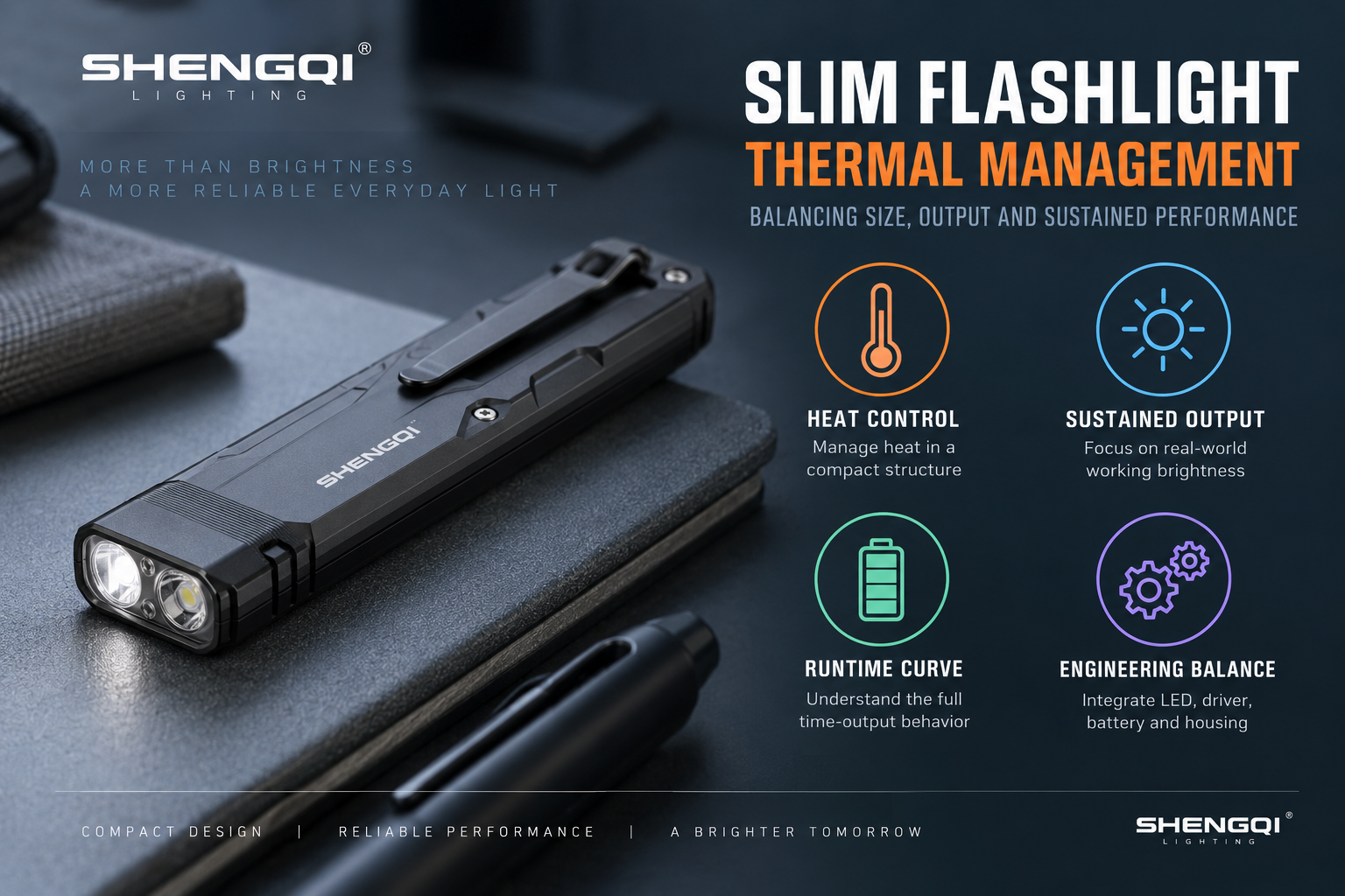

Why Slim Flashlights Reach Thermal Limits Earlier
A slim flashlight places several competing requirements into a restricted package: LED power, driver electronics, battery volume, controls, structural material and a path for heat to leave the source. Reduced thickness can make thermal spreading, battery clearance, PCB placement and component separation more difficult even when the external front and back surfaces are relatively large.
Slim designs do not always have less external surface area; the challenge is that reduced thickness and internal packaging can limit thermal mass, cross-sectional heat flow and the space available for separating heat-sensitive components.
That is why slim and flat EDC flashlight product range decisions should be evaluated as packaging-and-thermal problems together, not as a simple thin-versus-thick comparison.
Where Does the Heat Inside an LED Flashlight Come From?
The battery supplies electrical energy. The LED converts part of that energy into visible light, but the conversion is not perfect, so heat is generated around the LED junction and package. The driver and other electronics also produce losses while regulating current or converting voltage. At high current draw, the battery itself can develop internal heating because of its electrical resistance. Charging circuitry can add another heat source during charging.
The relevant heat sources can therefore include the LED package, driver electronics, PCB, battery and charging circuit. Their relative contribution depends on the specific product architecture and operating state.
BATTERY ENERGY → ELECTRONICS → LED → LIGHT + HEAT
Additional losses: Driver Loss + Battery Loss → Additional Heat
Simplified engineering model only. It does not represent a fixed energy percentage for a specific flashlight.
A Flashlight Thermal Path Is a Chain, Not One Material
A simplified conductive path can be described as:
If one interface presents relatively high thermal resistance, it can become a bottleneck even when the housing material itself conducts heat well. PCB design and the connection between the light source and the surrounding structure therefore matter alongside housing material. General LED thermal guidance from ams OSRAM thermal-management guidance similarly treats PCB-level heat spreading as part of the system.
The body material matters only after heat can reach the body efficiently.
Thermal Mass and Surface Area Solve Different Problems
Thermal mass affects how quickly the structure changes temperature as it absorbs heat. More mass can delay a temperature rise, but it does not remove the heat. Surface area influences heat transfer from the body to its surroundings, together with airflow, geometry, surface-to-ambient temperature difference and hand contact.
More surface area is therefore not automatically equivalent to better cooling under every condition. Likewise, simply adding metal is not free: it can increase weight, material use, cost and pocket burden. Adding metal is not a free thermal solution.
The engineering target is a workable balance between thermal performance and carry. A flat architecture may expose useful front and back area while still having limited cross-section for internal heat spreading.
| Buyer Wants | Potential Engineering Cost | Question to Resolve |
|---|---|---|
| Thinner Body | Less packaging freedom and thermal mass | Where will heat spread and components fit? |
| Higher Turbo Output | Higher thermal load | How long is peak output useful? |
| Longer Sustained Output | Thermal, power and size demand | What stable level is actually required? |
| Larger Battery | Consumes internal volume and adds mass | What duty cycle justifies it? |
| Lower Weight | Less structural or thermal mass | Which mass can be reduced safely? |
| More Functions | More PCB, controls and internal crowding | Which functions justify their volume? |
| Cooler Grip | May constrain heat-spreading strategy | Where should heat be rejected? |
Higher Output Increases the Thermal Budget the Design Must Manage
Increasing LED current can increase light output, but it also increases the heat that the electrical and mechanical design must handle. Driver efficiency matters because conversion losses become additional heat inside the product. The correct efficiency has to be measured for the actual circuit, input condition and operating point rather than assumed from a generic percentage.
Peak output is an electrical and thermal operating point, not a permanent promise of identical brightness. The same emitter can behave differently when placed on another PCB, driven at another current or connected to a different thermal path and housing.
Emitter choice is only one part of the thermal system. Buyers evaluating handheld flashlight platforms should therefore avoid comparing LEDs without the surrounding architecture.
The Battery Is Part of the Thermal System Too
Battery heating can be influenced by current draw, internal resistance, state of charge, cell condition and ambient temperature. No battery type should be assumed to run hotter or cooler in every flashlight without test evidence.
In a slim design, the LED, driver and battery may be physically closer because the product provides less freedom to separate subsystems. That does not mean the battery automatically overheats. It means the layout should avoid unnecessary concentration of heat around temperature-sensitive components and should be evaluated under realistic high-load conditions.
Internal layout should avoid unnecessary heat concentration around heat-sensitive components.
Turbo Output and Sustained Output Are Different Specifications
Peak or Turbo output is a high-output operating point that the product can reach under defined conditions. Sustained output describes the output region the light can maintain after thermal regulation, battery effects or other control behavior have changed the initial operating point.
START → TURBO PEAK → THERMAL RISE → STEP-DOWN → SUSTAINED REGION → BATTERY DECLINE → LOW-VOLTAGE BEHAVIOR → END
Why Does a Flashlight Step Down From Turbo?
Temperature-Based Regulation: output changes in response to a measured thermal condition. Not every flashlight uses a temperature sensor.
Timed Step-Down: the controller changes output after a predefined operating interval.
Voltage / Battery Limitation: declining battery voltage or available current can prevent the same output from being maintained.
Current / Protection Logic: driver, battery or protection circuitry may limit the operating point.
Combined Regulation: a real product may use more than one of these mechanisms.
Abrupt vs Gradual Regulation
An abrupt step-down creates a clear transition between operating states. Gradual regulation changes output more progressively. Some applications may benefit from a predictable hard transition; others may value a less noticeable adjustment. Step-down behavior should match the application.
How to Read a Flashlight Runtime Curve
A runtime curve places time on the X-axis and light output or relative output on the Y-axis. The buyer should look for seven stages: Initial Output, First Step-Down, Sustained Plateau, Secondary Regulation, Battery Decline, Low-Voltage Behavior and the defined End Point.
A single runtime number hides the shape of the performance curve.
T0 → PEAK → FIRST REGULATION EVENT → SUSTAINED REGION → BATTERY DECLINE → END CONDITION
T0: starting state and initial output. Peak: headline high-output region. First Regulation Event: when output first changes materially. Sustained Region: the level useful for longer operation. Battery Decline: later power-related reduction. End Condition: the test's defined stopping criterion.
Illustrative curve structure — not measured data from a specific flashlight.
Three Conceptual Runtime Profiles
Useful where brief maximum output matters more than maintaining that level continuously.
May fit tasks where predictable sustained illumination matters more than the highest initial peak.
Output decreases progressively as the system and battery move through the operating cycle.
Conceptual comparison only. No profile represents measured performance of a specific model.
Which is better depends on use. Short inspections may value a brief high peak. Continuous work may value a stable plateau. Emergency backup may prioritize predictable lower-mode duration. Everyday carry may require a balance between them.
A Runtime Claim Is Meaningful Only When the Test Conditions Are Clear
A buyer should ask: Which mode was tested? What was the starting output? Was there a step-down? What battery or cell configuration was used? Was the battery fully charged or otherwise preconditioned? What was the ambient temperature? Was the light actively cooled? What defined the end of runtime? Was output recorded continuously or checked only at intervals?
The current ANSI/PLATO FL 1-2025 announcement specifically adds standardized treatment for short-duration elevated brightness such as Turbo/Boost. Buyers making FL 1 comparisons should request the applicable method and test record rather than guessing how a peak value relates to a runtime number.
| Marketing / Spec Claim | What the Buyer May Assume | What the Buyer Should Verify |
|---|---|---|
| Maximum Output | Brightness is continuously available | Peak duration and subsequent output |
| Runtime | Output is constant for the full duration | Complete time-output curve and endpoint |
| Temperature Controlled | A specific sensor strategy is used | Actual control method and relevant sensing point |
| Constant Current | Brightness remains perfectly constant | Output behavior across battery and thermal conditions |
| Sustained Brightness | One fixed level is held indefinitely | Defined interval, output profile and environment |
| High-Efficiency Driver | Electronic heat is negligible | Project-specific efficiency and loss measurements |
Material Conductivity Matters, but Contact Surfaces Often Decide Whether Heat Can Use It
Aluminum can provide a useful structural and conductive path, but aluminum construction alone does not prove good thermal management. Polymer structures can reduce weight, provide electrical insulation or reduce direct heat sensation at user-contact surfaces. Mixed structures can combine internal metal heat spreading with different external materials.
Thermal design is a system problem, not a single-material contest.
Contact flatness, contact area, mounting pressure, thermal interface design and PCB seating can all change how effectively heat reaches the next part of the structure. Different products may use different interface solutions; thermal paste is not a universal requirement.
PCB Layout Can Create or Remove Thermal Bottlenecks
LED-board position, driver placement, copper area where applicable, thermal vias where applicable, battery proximity, charging circuitry, sensor placement and wire routing all interact with the mechanical structure. A larger PCB is not automatically better. Electrical layout and mechanical thermal design must be reviewed together.
If temperature sensing is used, sensor placement matters because a sensor near the LED, driver, battery or housing may represent a different thermal state. There is no universal best location. The sensor should measure a location relevant to the control objective.
Driver efficiency also belongs in this review: conversion losses create heat, but the relevant value should come from the actual circuit and operating condition rather than a generic efficiency claim.
The Flashlight Body Is Both a Heat Sink and a User Interface
A housing that becomes warm can indicate that heat is moving outward, but surface warmth alone does not prove the internal thermal path is good. Conversely, a cool exterior does not prove the internal LED, driver or battery area is cool. The engineering review should consider internal temperature, external surface temperature, grip comfort and sustained output together.
Grip Zone vs Primary Heat-Rejection Zone
The area near the LED may benefit from efficient heat spreading, while the area held for extended periods has a separate comfort requirement. Their relationship should be considered during industrial design rather than discovered only after tooling.
When Is a Warm Flashlight Normal, and When Does It Require Investigation?
Expected thermal behavior: temperature rises during demanding operation and is accompanied by understandable, repeatable regulation. Requires investigation: abnormal localized heating, unstable output, unexpected shutdown, inconsistent behavior between samples or unexplained heating concentrated around the battery area. These observations call for engineering review; they are not, by themselves, a diagnosis of product danger or defect.
Five Mistakes Buyers Make When Evaluating Slim Flashlight Performance
01. Comparing Peak Lumens Without Comparing Sustained Output
Peak output shows one operating point, not the complete duty cycle. Two products with similar headline lumens may reach very different post-regulation levels. Buyers should compare the time-output curve and the usable plateau. The sustained region often matters more for continuous work.
02. Treating Every Step-Down as a Defect
Step-down can be intentional thermal, timed or power-related control. Its presence alone does not indicate poor quality. Buyers should identify the trigger and resulting brightness level. Consistency and application fit matter more than whether a transition exists.
03. Comparing Runtime Numbers Without Matching Test Conditions
Runtime values measured with different batteries, environments, starting states or cooling conditions are not directly comparable. A single duration also hides output changes during the test. Request the curve and test conditions together. The question is both how long the light operated and what output it delivered.
04. Assuming an Aluminum Body Automatically Solves the Thermal Problem
Conductive housing material is useful only when the internal thermal path can deliver heat into it effectively. Contact area, mounting, PCB architecture and geometry all influence that path. A material label cannot replace an engineering review. Ask how the LED-to-body path is constructed and verified.
05. Approving One Excellent Sample Without Checking Production Consistency
An engineering sample can perform well while later units vary because of component revision, contact, assembly or tolerance differences. Buyers should compare production-representative samples with the approved configuration. Batch verification should then follow the buyer's quality requirements and production risk. One good sample is evidence, not proof of every future unit.
What B2B Buyers Should Verify Before Approving a Slim Flashlight
Thermal / Runtime Verification Matrix
| Verification Area | Buyer Question | Test Condition | Evidence | Risk if Unclear |
|---|---|---|---|---|
| 1. Starting Output | What output exists at T0? | Defined mode and battery state | Output record | Peak unclear |
| 2. Turbo Duration | How long before material regulation? | Defined environment | Time-output data | Peak misinterpreted |
| 3. Step-Down Trigger | Thermal, timed, voltage or combined? | Operating mode defined | Control description | Behavior unexplained |
| 4. Sustained Output | What level follows regulation? | Same runtime test | Sustained-region data | Working brightness unknown |
| 5. Runtime Curve | What is the complete profile? | Defined test method | Time-output graph | Duration hides behavior |
| 6. Ambient Temperature | At what ambient condition? | Recorded environment | Test record | Thermal headroom unclear |
| 7. Battery Configuration | Which approved cell/configuration? | Defined battery | Battery identity | Results not reproducible |
| 8. Starting State of Charge | How was the battery preconditioned? | Defined start state | Precondition record | Starting conditions vary |
| 9. Driver Behavior | How does regulation change? | Defined load state | Electrical/output record | Cause misidentified |
| 10. Surface Temperature | Where and how was it measured? | Defined measurement points | Temperature data | Comfort unclear |
| 11. Battery-Area Temperature | How does the battery region behave? | Representative operation | Location-specific data | Heat concentration unknown |
| 12. Low-Voltage Behavior | How does output end? | Full discharge profile | Curve/end record | Endpoint unclear |
| 13. Sample-to-Sample Variation | Do samples regulate consistently? | Matched sample conditions | Comparison records | Variation hidden |
| 14. Production-Representative Sample | Does production match engineering intent? | Production process | Representative sample test | Prototype-only confidence |
| 15. Batch Verification Plan | How will later production be checked? | Buyer-defined risk plan | Inspection/test plan | Drift may go unnoticed |
Buyer Test Flow
The actual test method should be selected according to the product, claim, applicable standard and project requirement. This sequence is a procurement workflow, not a universal laboratory standard.
Useful evidence can include time-output data, environment, battery details, mode, temperature data where relevant, sample revision, test date and method. A report that says only “Runtime: 4h” cannot show what happened to high-mode output during those hours.
Relevant portable-light testing and quality-control capabilities can support this evaluation, but acceptance criteria still need to be defined for the specific project.
Slim Flashlight Thermal & Runtime Buyer Matrix
| Area | What to Ask | Why It Matters | Evidence |
|---|---|---|---|
| 1. Peak Output | What is the measured starting level? | Defines headline performance | Output test |
| 2. Turbo Duration | How long before regulation? | Separates peak from working level | Time-output data |
| 3. Step-Down Type | What controls the transition? | Explains repeatability | Control specification |
| 4. Sustained Output | What level follows the peak? | Shows long-use brightness | Curve plateau |
| 5. Runtime Curve | Can we see the full profile? | Duration alone is incomplete | Graph/data |
| 6. Ambient Temperature | What was the environment? | Changes thermal headroom | Test record |
| 7. Battery | Which cell/configuration? | Changes electrical behavior | Battery specification |
| 8. Driver | How is output regulated? | Affects heat and output | Electrical behavior |
| 9. Thermal Path | How does heat reach the body? | Reveals bottlenecks | Design review |
| 10. Surface Temperature | Where is it measured? | Links heat rejection to handling | Temperature record |
| 11. Grip Area | How does the hand-contact zone behave? | User comfort matters | Representative handling test |
| 12. Sample Variation | Do several samples behave alike? | Shows process variation | Comparison data |
| 13. Production Sample | Does production match approval? | Connects design to manufacturing | Production-representative test |
| 14. Batch Verification | How will later batches be checked? | Controls production drift | Buyer-defined quality plan |
Sample Performance Is Not Automatically Production Performance
LED revision or bin, driver components, PCB assembly, battery, mechanical tolerance and thermal-interface assembly can all affect the result. Even when the design is correct, inconsistent mounting, contact, interface material or fastening can create sample-to-sample thermal variation. Thermal performance is partly a manufacturing-consistency problem.
A production-representative sample should therefore be checked against the approved engineering result, followed by a batch verification plan based on the buyer's quality requirements and production risk. No universal sampling percentage is assumed here.
Manufacturing infrastructure supports production capability; thermal performance still requires product-specific engineering and verification. SHENGQI's flashlight manufacturing capabilities provide the production context for translating an approved configuration into repeatable manufacturing.
How OEM/ODM Buyers Should Define Thermal Performance Before Approving a Slim Flashlight
Do not send the supplier only a peak lumen target. A useful brief should define the Target User, Use Case, Required Peak Output, Required Sustained Output, Typical Operating Duration, Body Size / Thickness Direction, Weight Direction, Battery Architecture, LED / Driver Architecture, Step-Down Behavior, Surface-Temperature Requirement, Test Environment, Runtime Evidence, Sample Revision and Production Verification.
“Need slim EDC flashlight, very bright, long runtime, no heat.”
Target Application · Body Size Direction · Peak Output Priority · Sustained Output Priority · Typical Use Duration · Battery Direction · Surface Comfort Requirement · Step-Down Expectation · Test Environment · Estimated Quantity
“No heat” is not a meaningful engineering target. Electronic products can generate heat during operation. The useful requirement is acceptable thermal behavior under defined operating conditions.
For compact portable-lighting projects, thermal behavior needs to be reviewed across industrial design, electronic design, PCB layout, battery placement and verification rather than treated as a single-component specification. SHENGQI supports these development stages through its OEM/ODM portable lighting development process.
Infrastructure such as CNC machining, SMT and assembly capacity can support implementation, but it does not prove a thermal claim by itself. The product still needs engineering evidence and production-representative verification.
Buyers evaluating alternative architectures can also review the broader portable lighting product range before deciding whether an existing form factor or new development path better fits the project.
Frequently Asked Questions About Slim Flashlight Thermal Management
1. Why do slim flashlights get hot quickly?
Slim flashlights can encounter thermal limits quickly because a high-output LED, driver, battery and other electronics are packaged into a structure with limited thickness. Reduced thickness can constrain thermal mass, internal component separation and the cross-sectional path available for spreading heat. That does not mean every thin flashlight has poor heat dissipation. A flat body may still provide useful external surface area. The actual result depends on how effectively heat travels from the LED and electronics through the PCB, interfaces and housing, how much power the light is using and how its regulation responds as temperature rises.
2. Does a thinner flashlight always have worse heat dissipation?
No. Thickness is only one part of the thermal architecture. Slim designs can have relatively large front and back surfaces, while a thicker product can still contain an inefficient internal thermal path. The important variables include output power, driver loss, LED-to-PCB connection, contact area, body geometry, material, thermal mass, airflow and regulation. A thinner design usually gives engineers less freedom for internal spacing, battery clearance and heat-spreading structures, so the packaging problem can become harder. Performance should therefore be measured through temperature and output behavior rather than inferred from thickness alone.
3. Is a warm flashlight a sign of poor quality?
Not necessarily. A warm housing can indicate that heat generated inside the light is reaching the external body, where it can transfer to the environment. However, surface warmth by itself does not prove good thermal engineering, because internal component temperature, localization of heat, user comfort and output stability also matter. A cool housing likewise does not prove that the LED or driver is operating cool. Buyers should investigate abnormal localized heating, unstable output, unexplained shutdowns or inconsistent behavior between samples. Thermal quality should be judged from the complete system rather than from the simple question of whether the body feels warm.
4. Why does a flashlight step down from Turbo mode?
A flashlight may reduce output because of temperature-based regulation, a timed control rule, declining battery voltage, current limitation, protection logic or a combination of those mechanisms. Not every product uses a temperature sensor, and not every step-down is triggered by the same event. A planned reduction may help control component temperature, battery load, surface comfort or later output stability. Buyers should therefore identify what triggers the transition, how quickly it occurs, whether the reduction is abrupt or gradual and what output remains afterward. The presence of step-down is less informative than its cause, timing, magnitude and repeatability.
5. What is the difference between peak output and sustained output?
Peak output is the high-output operating point a flashlight can reach under specified starting conditions. Sustained output is the brightness region available after heat, battery behavior and control logic have affected that initial state. A product can therefore have an impressive peak while settling to a much lower working level, or it can begin at a more moderate output and remain steadier for longer. Neither profile is automatically better. Short inspections and continuous work create different priorities. Buyers should compare the full time-output curve so that a Turbo number is not mistaken for the brightness available during the entire reported runtime.
6. How should buyers read a flashlight runtime curve?
Start at the initial output, then identify the first regulation event and the level that follows it. Look for a sustained plateau or gradual regulation, later battery-related decline, low-voltage behavior and the defined end of the test. Then check the conditions behind the graph: battery configuration, starting charge state, ambient temperature, product orientation and whether external airflow or active cooling was used. Those details determine what the curve represents. A long duration with low post-step-down output is different from a shorter period of stronger sustained brightness, even if both products publish attractive runtime figures.
7. Does an aluminum body automatically provide good thermal management?
No. Aluminum can provide a useful conductive structure, but the internal heat still has to reach that structure. LED-board mounting, PCB seating, contact flatness, contact area, interface design and mechanical geometry can all create or reduce thermal resistance. An aluminum shell surrounding a poorly connected heat source cannot fully compensate for a major internal bottleneck. Conversely, mixed material designs can use internal metal paths while using polymer externally for weight, insulation or user-contact reasons. The correct comparison is therefore the complete heat-transfer system and measured behavior, not the housing material label alone.
8. What should OEM/ODM buyers test before approving a slim high-output flashlight?
Buyers should record starting output, Turbo duration, step-down behavior, sustained output, complete runtime curve, ambient temperature, battery configuration, starting battery state, surface and relevant internal-area temperature where applicable, low-voltage behavior and sample variation. Tests should identify the sample revision and disclose external cooling or other conditions that could change the result. A production-representative sample should later be compared with the approved engineering sample because thermal contact, PCB assembly, components, battery and mechanical tolerances can affect production behavior. The final batch-verification plan should follow the buyer's quality requirements and product risk rather than an invented universal sampling percentage.
Sustained Performance Is the Evidence That Matters After the Peak
A slim flashlight is not thermally successful because it remains cold, and it is not automatically unsuccessful because its output steps down. The meaningful question is whether the thermal path, regulation behavior, sustained output and runtime curve match the intended use—and whether those results can be reproduced from sample to production. When a buyer asks, “How long can this light deliver its headline output?” the next questions should be: At what output level, under what temperature, after what step-down and using what test conditions?
Shengqi Lighting is preparing a new Compact EDC Flashlight direction for the 140th Canton Fair. Visit Booth 16.4F25 from October 15–19, 2026 for an early look. Final specifications will be released after engineering validation.
Developing a Slim or Compact Flashlight With a Defined Sustained-Output Target?
For the first technical review, prepare your Target Market, Application, Body Size / Thickness Direction, Peak Output Requirement, Sustained Output Requirement, Typical Operating Duration, Battery Direction, Thermal / Surface-Comfort Requirement, Estimated Quantity and Target Timeline.
Review SHENGQI LIGHTING's custom flashlight development capabilities.
Contact SHENGQI LIGHTING for an OEM/ODM technical evaluation at sales@shengqilight.com.
Contact SHENGQI LIGHTING