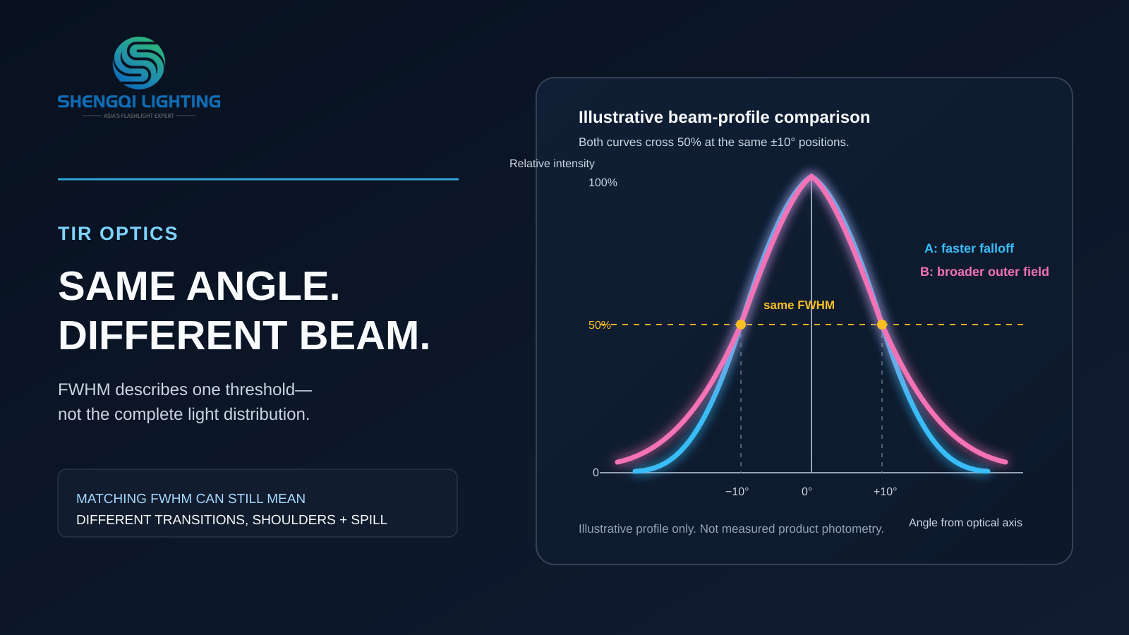
Imagine two hypothetical TIR optics, both listed as 20°. Sample A appears to move quickly from a concentrated center to a darker outer area. Sample B still shows noticeable illumination outside its center. Neither result necessarily contradicts the 20° data. A beam angle usually describes the width of intensity at one defined point, not the complete hotspot, transition, spill or total light distribution. To compare TIR optics properly, buyers need the angle definition, the LED-and-lens combination, the full distribution and a task-relevant sample check.
Direct answer: TIR optics use refraction and, in many designs, total internal reflection to redistribute LED light. The quoted beam angle is useful, but it is only one descriptor. Two optics can have the same FWHM beam angle while producing different center intensity, shoulder shape, outer distribution and symmetry.
What Are TIR Optics in Portable Lighting?
TIR means Total Internal Reflection. In portable LED lighting, a TIR optic is commonly shaped to redirect light with a combination of refraction and internal reflection. This gives designers another way to control how light leaves the LED and reaches the target area.
Total internal reflection occurs when light travels from a higher-refractive-index material toward a lower-refractive-index boundary and reaches that boundary above the relevant critical angle. The angle is measured relative to the surface normal. Not every ray entering a TIR optic follows the same path, and not every ray is internally reflected. A TIR optic is therefore not a claim of complete light capture, fixed efficiency or one predetermined beam shape.
A TIR lens may create a concentrated spot, a medium beam, a wide distribution or an asymmetric pattern, depending on the optical design and LED combination. The practical question for a flashlight, headlamp or work light is not simply “Does it use TIR optics?” It is “Where does the useful light go, and how does that distribution support the intended task?”
What Does a Beam Angle Actually Measure?
Many TIR optic data sheets use FWHM, short for Full Width at Half Maximum. The peak luminous intensity is identified first. The two angular positions where intensity falls to 50% of that peak are then located. The complete angular distance between those positions is the FWHM beam width. Carclo’s explanation of beam angle and FWHM provides a useful reference for this distinction.
The phrase “50%” here means 50% of the peak luminous intensity. It does not mean that 50% of the total lumens are inside that angle. It also does not state how much light exists beyond the FWHM points, how sharply the beam transitions, or whether the beam has shoulders or secondary peaks.
For a symmetrical single-peak distribution with a 20° FWHM, the half-maximum points may be understood as approximately -10° and +10° from the optical axis. That is a full beam width, not two separate 20° half angles. However, buyers should still confirm whether a document reports full width, half angle, a different intensity threshold or a specific measurement plane.
For an oval or asymmetric beam, one angle may be insufficient. The relevant data may need separate measurements in different directions or planes. A single number cannot describe every part of an asymmetric distribution.
Why Two TIR Optics With the Same FWHM Can Look Different
FWHM only compares the positions where each distribution crosses its own 50% peak-intensity level. It does not define the curve between the center and that point, and it does not define the curve outside it. This is why matching beam angles do not automatically create matching beam patterns.
| Shared information | Possible pattern difference | What the comparison supports | What it does not support |
|---|---|---|---|
| Both optics are listed with the same FWHM. | One pattern may fall away rapidly beyond the half-maximum points, while another has a broader shoulder or more outer illumination. | The nominal half-maximum width is the same. | Which optic is absolutely brighter, has more total lumens or suits every task. |
The center-to-edge transition may be more defined in one optic and more gradual in another. One pattern may include a stronger shoulder outside the central hotspot. Another may show a secondary peak or a more visible outer field. These characteristics can affect what a user sees on a nearby wall, on a work surface or at a target distance.
A second descriptor sometimes used is FWTM, or Full Width at Tenth Maximum. It measures the full angle between points at 10% of peak intensity. This can help reveal how far lower-intensity light extends beyond the central region. LEDiL’s discussion of FWHM and FWTM also illustrates why two optics can share the same FWHM while differing outside the central beam. FWTM is useful context, but it is not the edge of all light and does not replace the complete luminous-intensity distribution.
Outer light is not automatically wasted light. It may help a user orient themselves around a close-range task. In another application, that same outer distribution may create unwanted reflections, light on adjacent surfaces or less precise emphasis on the intended target. The correct choice depends on the target and working environment.
What Separately Peak-Normalized Curves Can and Cannot Show
A separately peak-normalized distribution plot sets the highest point of each curve to 100%. This is valuable for comparing relative shape: where intensity falls, whether the beam has a shoulder and how it behaves away from the optical axis. But when each curve is independently normalized to its own peak, the plot alone cannot show absolute candela, total lumens or illuminance on a target.
Data expressed in cd/lm use a different reference. They can support a quantitative comparison only when the stated lumen basis, corresponding LED, optic configuration and measurement conditions are understood and comparable. They should not be treated as though every curve has simply been reset to 100%.
Neither a separately peak-normalized plot nor a cd/lm value should be treated as finished-flashlight performance without confirming the actual LED, optic, mechanical arrangement and measurement conditions of the final configuration.
When Reading TIR Optic Data, Look Beyond the Nominal Angle
A data sheet is most useful when each item is understood as part of a larger optical configuration. The following questions help a product manager or buyer identify what the document explains and what still requires confirmation.
| Information shown | What it helps explain | What it cannot establish alone | What to request next |
|---|---|---|---|
| Nominal beam angle | A quick indication of concentration or spread. | Hotspot shape, spill, absolute output or a match to the final flashlight. | The angle definition, full width or half angle, and stated threshold. |
| FWHM | The width between the two 50%-of-peak intensity points. | Total lumen share inside the beam or behavior beyond the half-maximum points. | A full beam plot and the specific LED used for the result. |
| FWTM, if provided | How lower-intensity light extends around the center. | The final edge of all visible light or task performance at distance. | The complete angular distribution and sample observations. |
| Separately peak-normalized distribution (%) | Relative beam shape, shoulders, asymmetry and intensity falloff. | Absolute candela, total lumens or target illuminance from the plot alone. | Absolute photometric data if quantitative comparison is needed. |
| cd/lm or other stated photometric baseline | Quantitative intensity comparison when the lumen basis and test conditions are comparable. | Final target illuminance without distance, geometry and final-product configuration. | Lumen reference, LED source, drive condition and measurement details. |
| LED, lens version and measurement conditions | Whether the listed beam is relevant to the intended configuration. | That a different LED or final housing will reproduce the same beam. | The intended LED, optical configuration and final-product sample check. |
The Lens Is Part of a System, Not an Independent Beam Guarantee
A TIR optic data sheet belongs to a particular optical setup. Changing the LED package, light-emitting surface, lens version, surface treatment, installation relationship, front window or surrounding mechanical structure can change the resulting distribution. This is why lens data should not be copied into a finished flashlight specification without checking the actual configuration.
A wall beam can be a useful observation tool, but it is not a complete photometric measurement. Keep distance, background, exposure and white balance controlled if samples are compared visually. Automatic camera exposure can make one wall photo appear brighter or darker without proving a change in absolute luminous intensity.
For background on how reflector and TIR architectures differ at a high level, see our existing article on SMO, OP and TIR flashlight optics. For broader terms such as luminous intensity and related metrics, see the flashlight optical metrics guide.
Write “Narrow Beam” as a More Useful Optical Requirement
“We need a narrow beam” is a starting point, not a finished optical requirement. Different people may mean a tighter hotspot, less peripheral illumination, better target definition at distance or a smaller apparent spot on a nearby surface.
Example requirement wording
“The light should emphasize a target at the intended working distance, with a concentrated center and controlled outer illumination. Please evaluate the center-to-edge transition, the required peripheral visibility, directions where unwanted light should be limited, the available head-space constraints, and the LED or current sample information used for comparison.”
For a focused development discussion, provide:
- The target use and working distance.
- The target area that should receive the strongest light.
- How much peripheral visibility is useful around that target.
- Directions or surfaces where unwanted light may create glare or distraction.
- The available space for the light head, plus any existing LED, lens or sample reference.
Discussing a TIR Optic Direction With SHENGQI LIGHTING
A meaningful portable-lighting discussion starts with the desired distribution, source and product constraints rather than a single angle number. SHENGQI LIGHTING’s published development services include optical-engineering work and reflector/TIR lens simulation alongside industrial and electronic design. Explore the SHENGQI LIGHTING development services.
This capability description does not mean every SHENGQI LIGHTING product uses TIR optics or that a simulation replaces final finished-light evaluation. It means the discussion can begin with the target distribution, LED direction, housing space and sample evidence needed for the intended portable-lighting task.
FAQ
Does a 20-degree TIR lens keep all light inside 20 degrees?
Not necessarily. If 20° is an FWHM value, it describes the width between the two points at 50% of peak intensity. Lower-intensity light may extend beyond that width.
Can two TIR optics have the same beam angle but different spill?
Yes. Similar FWHM values can still accompany different shoulder shapes, falloff rates, secondary features and lower-intensity outer distribution.
Can changing the LED change a TIR lens beam?
Yes. The LED package and light-emitting surface are part of the optical configuration. A beam result published for one LED-and-lens combination should not be assumed for another combination.
Can separately peak-normalized plots show absolute intensity?
When each curve is separately normalized to its own peak, the plot alone cannot show absolute intensity. Data in cd/lm use a different reference, so interpretation requires the stated lumen basis and matching source conditions. Neither should be treated as finished-flashlight performance without confirming the actual configuration.
Discuss Your Target Beam Distribution
For a TIR optics discussion, share the target use, working distance, required center and peripheral illumination, directions where light should be limited, available light-head space, and any LED or existing sample information. This gives the engineering conversation more meaning than a beam-angle request alone.
Email sales@shengqilight.com to discuss a suitable portable-lighting platform or product-development direction.